Summary of An isolated analog input for Arduino
This article presents an opto-isolated analog input circuit for Arduino using a voltage-to-frequency converter (LM331), ideal for industrial 4-20mA sensors to mitigate noise and ground potential issues. The design converts analog signals into frequency pulses via an optocoupler, requiring only three wires to connect to the Arduino. It supports input voltages from 20mV to 5V or currents of 4-20mA, with adjustable power supply requirements for different voltage ranges.
Parts used in An isolated analog input for Arduino:
- Arduino board
- LM331 voltage-to-frequency converter
- Opto-coupler
- Resistors (R2, R3, R4, R6, P1, R7, C3, pull-up resistor)
- Jumper W1
- Voltage regulator (7808 or 7815)
- Power supply
This blog is dedicated to electronic projects and software due to the author’s enthusiasm for these activities. The main aim is to share to other enthusiasts the experience in electronic design of the author who disclaims all responsibility. All presented projects are realized and fully tested by the author who intends to preserve the intellectual property of the projects or information, whose utilization is intended only for non-professional purposes.
An isolated analog input for Arduino
by Giovanni Carrera, rev. 28/05/16
A voltage to frequency converter can realize an opto-isolated analog input for Arduino or other microcontroller systems. This circuit is particularly suitable for industrial control plants with 4-20mA sensors.
Introduction
The signals from field sensors can be affected by noise generated by power surges, lightning strikes or other EMI (Electromagnetic Interference) sources and also by ground potential differences. One method to avoid most of these problems is to use a complete isolation from the field.
The isolation of an input sensor will require a separate power supply to power the field device and the circuit that realize the insulation itself.
In the 80s, when the microcontrollers hadn’t digital to analog converters (ADC) integrated, I had designed a system with voltage to frequency converters to achieve high-resolution analog inputs and an easy true isolation with the field sensors. Only drawback was the low sampling rate, but usually high frequencies aren’t required in industrial plants.
The following figure shows a three channels board that I designed many years ago for a 6502 control system.
The circuit
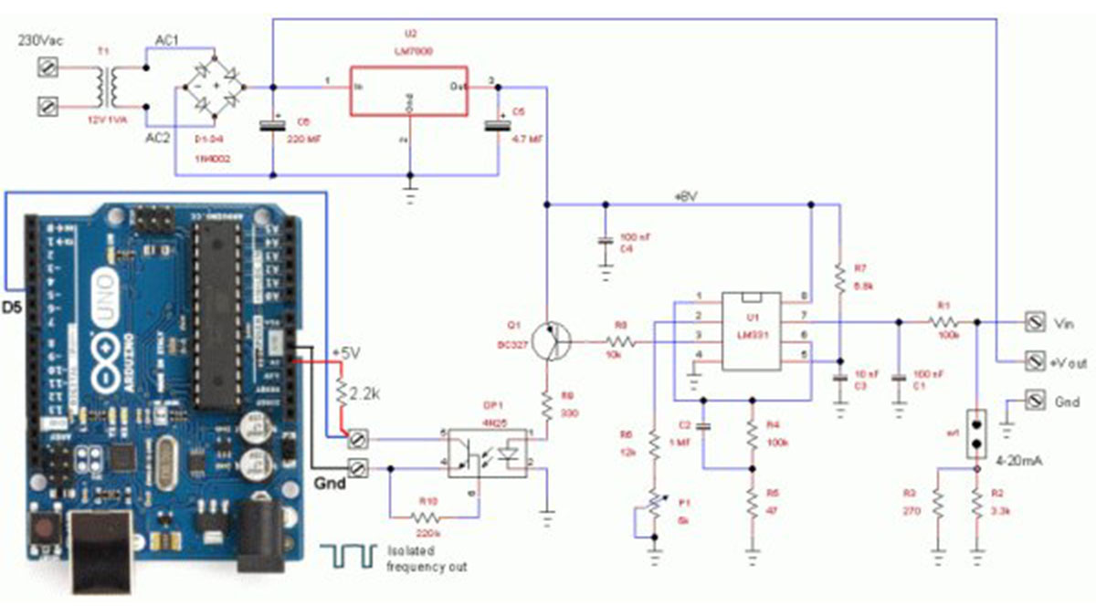
So I think up to use this circuit also with Arduino. The diagram of Figure 2 shows the circuit that accepts an input voltage from about 20mV to 5V or a current of 4 to 20 mA (with the jumper W1 inserted). The two resistors in parallel R2 and R3 give a value of about 250 ohms, in order to have 1V to 5V for 4mA to 20mA input.
Just three wires and a resistor are required to connect the circuit to the Arduino Uno. The output of the opto-coupler should be connected to the digital input D5 with a pull-up 2.2kW resistor connected to the +5V of Arduino.
If an input range of 10V is required, a 15V power supply is necessary, so you have to change the 7808 regulator with a 7815.
The resistor R10 reduces the switching time of the phototransistor.
The circuit of the converter is obtained from the datasheet of the LM331.
The output frequency is:
Fout = Vin*(R6+P1)/(2.09*R4*R7*C3)
This circuit, with the values used, has a conversion factor of about 1kHz/V.
The duration of output pulses is:
T = 1.1* R7*C3 = 74.8 [ms]
Hardware components
1x Arduino board
Passive components
Read more: An isolated analog input for Arduino
- How does this circuit achieve isolation?
The circuit uses an opto-coupler to create complete electrical isolation between the field sensor and the microcontroller, avoiding problems caused by noise and ground potential differences. - Can this circuit handle 4-20mA current sensors?
Yes, the circuit accepts a current of 4 to 20 mA when jumper W1 is inserted, utilizing parallel resistors R2 and R3 to convert the current to a voltage range. - What components are required to connect the circuit to the Arduino?
Only three wires and a resistor are required to connect the circuit to the Arduino Uno. - Where should the opto-coupler output be connected?
The output of the opto-coupler should be connected to digital input D5 with a 2.2kW pull-up resistor connected to the +5V of the Arduino. - How do I adjust the circuit for a 10V input range?
To handle a 10V input range, you must change the 7808 regulator to a 7815 and use a 15V power supply. - What is the conversion factor of this circuit?
With the values used in the design, the circuit has a conversion factor of approximately 1kHz/V. - Does this method offer high sampling rates?
No, while effective for isolation, the main drawback of this voltage-to-frequency approach is a low sampling rate, though high frequencies are usually not required in industrial plants. - What is the function of resistor R10?
Resistor R10 reduces the switching time of the phototransistor within the circuit.