
Summary of Smart Blind Stick using Arduino
Hugh Herr inspired this Arduino project: a smart cane for visually impaired users that senses obstacles with an ultrasonic sensor, detects ambient light with an LDR, and can be located remotely via a 433 MHz RF transmitter/receiver. An Arduino Nano reads sensors and the RF receiver ADC, outputs alerts via a buzzer (or vibration motor), and is powered from a 9V battery regulated to 5V by a 7805. The design uses a perf board for mounting; the RF trick detects repeated ADC values when the remote button is pressed.
Parts used in the Smart Blind Stick:
- Arduino Nano (any version)
- Ultrasonic Sensor HC-SR04
- LDR (light dependent resistor)
- Buzzer (or vibrator motor)
- LED
- 7805 voltage regulator
- 433 MHz RF transmitter
- 433 MHz RF receiver
- Resistors (including a 10K for the LDR divider)
- Push button (on RF transmitter)
- Perf board
- Soldering kit
- 9V batteries
Ever heard of Hugh Herr? He is a famous American rock climber who has shattered the limitations of his disabilities; he is a strong believer that technology could help disabled persons to live a normal life. In one of his TED talk Herr said “Humans are not disabled. A person can never be broken. Our built environment, our technologies, is broken and disabled. We the people need not accept our limitations, but can transfer disability through technological Innovation”. These were not just words but he lived his life to them, today he uses Prosthetic legs and claims to live to normal life. So yes, technology can indeed neutralize human disability; with this in mind let us use the power of Arduino and simple sensors to build a Blind man’s stick that could perform more than just a stick for visually impaired persons.
This Smart stick will have an Ultrasonic sensor to sense distance from any obstacle, LDR to sense lighting conditions and a RF remote using which the blind man could remotely locate his stick. All the feedbacks will be given to the blind man through a Buzzer. Of course you can use a vibrator motor in place of Buzzer and advance a lot more using your creativity.
Materials Required:
- Arduino Nano (Any version will work)
- Ultrasonic Sensor HC-SR04
- LDR
- Buzzer and LED
- 7805
- 433MHz RF transmitter and receiver
- Resistors
- Push button
- Perf board
- Soldering Kit
- 9V batteries
Circuit Diagram:
This Arduino Smart Blind Stick Project requires two separate circuits. One is the main circuit which will be mounted on the blind man’s stick. The other is a small remote RF transmitter circuit which will be used to locate the main circuit.
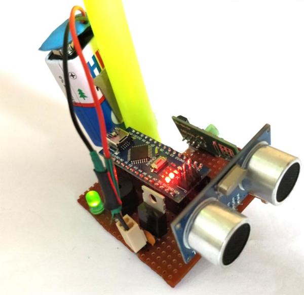
As we can see an Arduino Nano is used to control all the sensors. The complete board is powered by a 9V battery which is regulated to +5V using a 7805 Voltage regulator. The Ultrasonic sensor is powered by 5V and the trigger and Echo pin is connected to Arduino nano pin 3 and 2 as shown above. The LDR is connected with a resistor of value 10K to form a Potential divider and the difference in voltage is read by Arduino ADC pin A1. The ADC pin A0 is used to read the signal from RF receiver. The output of the board is given by the Buzzer which is connected to pin 12.
I have used a small hack to make this RF remote control circuit to work. Normally while using this 433 MHz module requires an Encoder and Decoder or two MCU to work. But, in our application we just need the receiver to detect if the transmitter is sending some signals. So the Data pin of the transmitter is connected to Ground or Vcc of the supply.
The data pin of the receiver is passed through an RC filter and then given to the Arduino as shown below. Now, whenever the button is pressed the Receiver output some constant ADC value repeatedly. This repetition cannot be observed when the button is not pressed. So we write the Arduino program to check for repeated values to detect if the button is pressed. So that is how a Blind person can track his stick. You can check here: how RF transmitter and receiver work.
I have used a perf board to solder all the connections so that it gets intact with the stick. But, you can also make them on a breadboard.

Read More: Smart Blind Stick using Arduino
- How does the stick detect obstacles?
The Ultrasonic Sensor HC-SR04 measures distance and its trigger and echo pins are read by Arduino Nano pins 3 and 2 to detect obstacles. - How is ambient light sensed?
An LDR forms a potential divider with a 10K resistor and the resulting voltage is read by Arduino ADC pin A1 to sense lighting conditions. - How can the blind person locate the stick remotely?
A 433 MHz RF transmitter/receiver pair is used; when the transmitter button is pressed the receiver produces repeated ADC values that the Arduino detects to indicate the stick is being located. - What powers the Smart Blind Stick?
The board is powered by a 9V battery regulated to +5V using a 7805 voltage regulator. - Which Arduino pin outputs the alert?
The buzzer is connected to Arduino pin 12 to provide feedback. - Do I need encoder/decoder for the RF modules?
No; the project uses a workaround by detecting repeated ADC values from the receiver when the transmitter data pin is tied to Vcc or GND, avoiding encoder/decoder use. - Can I replace the buzzer with something else?
Yes, the article states you can use a vibrator motor in place of the buzzer. - Where are the sensors and electronics mounted?
The components are soldered on a perf board which is mounted on the stick; a breadboard may be used during prototyping.