
Summary of How To Make A Simple Arduino Voltmeter Prototype
This instructable explains building a simple Arduino voltmeter using an Arduino Uno (or similar), a 128x64 OLED, and a two-resistor voltage divider to measure voltages beyond 5V. It covers resistor selection with examples for common ranges, wiring, required U8glib for the OLED, ADC limitations (10-bit, 0–1023), and cautions to measure only positive voltages. It notes higher-resolution ADCs give better accuracy and that negative-voltage measurement is covered in a separate gauss meter project.
Parts used in the Simple Arduino Voltmeter:
- Arduino Uno or similar microcontroller
- 128x64 OLED display
- Resistor R1 (value depends on desired voltage range)
- Resistor R2 (value depends on desired voltage range)
In this instructable, I’ll show you how to make a simple Arduino voltmeter. It can measure voltages in excess of 30VDC depending on how you configure it. The smaller the voltage range you want to measure, the more accurate that your meter will be. This project is going to be apart of a gauss meter that I am making to measure magnetic fields strength as well as magnetic field polarity. This instructable should provide a good base for a large number of different applications that will need the Arduino to monitor the voltage level of something.
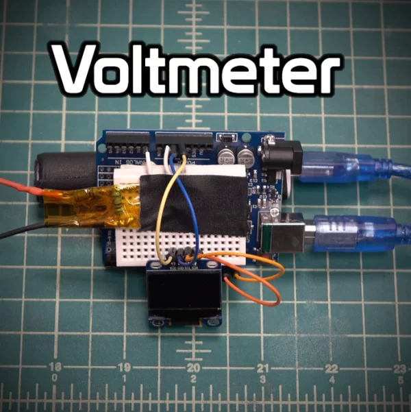
Step 1: What You Will Need
1. Arduino Uno or similar microcontroller.
2. 128×64 OLED display
3. Two resistors. The values depend on the range of voltages you want to measure
Step 2: Schematic
Wire up your components as shown and choose your resistor values based on the range you want to measure. For example, if you want to measure 0-10V then you could pick R1 as 100k and R2 as 100k. Be sure to measure your resistors before plugging the number into your program to ensure a more accurate measurement.
To calculate your desired voltage range you will need to use the following voltage divider formula.
Vout = (R2*Vin)/(R1+R2)
Vout will need to be 5V for the ADC and Vin will be the max voltage value that you want to measure.
Here are a few voltage range examples:
0-10V : R1=100k, R2=100k
0-15V : R1=100k, R2=50k
0-25V : R1=100k, R2=25k
0-55V : R1=100k, R2=10k
Step 3: Upload the Code
Before you upload the code, you will need to download the U8glib library from here if you are using an OLED display.
Step 4: How It Works
This voltmeter uses the Arduino’s analog to digital converter on the analog pin and convert 0-5 volts into a value from 0-1023. To measure more than 5 volts, you need use a voltage divider and calculate the voltage in your program. The problem with this is that the Arduino’s analog to digital converter still only has a resolution of 1024 points so the higher voltage you want to measure, the less accurate your voltmeter will be.
The ADC on the Arduino is a 10-bit ADC, meaning it only has the ability to detect 1,024 discrete analog levels. For my gauss meter I will probably use a microcontroller with a 16-bit ADC for 65,535 discrete levels and a overall more accurate meter.
Only use this voltmeter to measure positive voltages and never hook it up with the wrong polarity. In my gauss meter instructable, the Arduino will measure negative and positive values so wait for that to see how to measure negative values.
- What microcontroller is needed for the voltmeter?
An Arduino Uno or similar microcontroller is used in the project. - What display is used with the voltmeter?
A 128x64 OLED display is used and requires the U8glib library. - How many resistors do I need for the voltage divider?
Two resistors are required; their values depend on the voltage range you want to measure. - How do I calculate resistor values for the voltage range?
Use the voltage divider formula Vout = (R2 * Vin) / (R1 + R2) and ensure Vout is 5V for the ADC with Vin as the maximum voltage to measure. - What are example resistor pairs for common voltage ranges?
Examples given: 0-10V R1=100k R2=100k; 0-15V R1=100k R2=50k; 0-25V R1=100k R2=25k; 0-55V R1=100k R2=10k. - Do I need to measure my resistors before using them?
Yes, the article advises measuring your resistors before plugging the numbers into the program for better accuracy. - How does the Arduino ADC affect accuracy?
The Arduino uses a 10-bit ADC that converts 0-5V into values 0-1023, so higher measurement ranges reduce accuracy due to limited resolution. - Can this voltmeter measure negative voltages?
No, this voltmeter should only be used to measure positive voltages; negative measurement is handled in a separate gauss meter instructable.
