Summary of Hot Wire Foam Cutter – Arduino PWM
This article details a DIY hot wire foam cutter project featuring precise temperature control via PWM. The system utilizes an ATtiny85 Digispark microcontroller to regulate heat, housed within a plastic box and PVC pipes for wiring. The design includes a potentiometer for user adjustment and an LED indicator, allowing for efficient foam cutting with customizable settings based on the code provided.
Parts used in the Hot Wire Foam Cutter:
- Arduino UNO & Genuino UNO
- Atmel ATTiny85
- DigiSpark
- Plastic box for electronics
- Jumper wires (generic)
- IRF530
- Resistor 1k ohm
- Resistor 100 ohm
- Single Turn Potentiometer- 10k ohms
- BC547
- LED (generic)
- 7812
- Hot wire foam cutter
| Hardware components: | ||||||
 |
|
× | 1 | |||
 |
|
× | 1 | |||
 |
|
× | 1 | |||
|
× | 1 | ||||
 |
|
× | 1 | |||
|
× | 1 | ||||
 |
|
× | 5 | |||
 |
|
× | 2 | |||
 |
|
× | 1 | |||
|
× | 2 | ||||
 |
|
× | 1 | |||
|
× | 1 | ||||
|
× | 1 | ||||
STORY
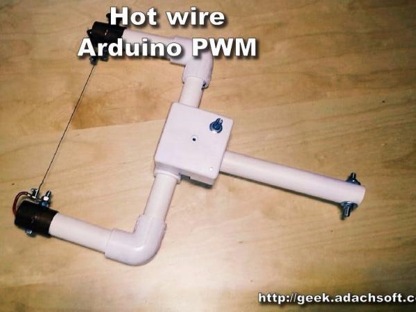
I did the hot wire foam cutter previously but I missed the temperature control. So that’s why I made a simple PWM control. The whole project was based on Arduino ATtiny85 Digispark. For this project I only needed three pins, so the ATtiny85 is fine. Also I carried the wires in the PVC pipes.
See more: Hot wire foam cutter – Arduino PWM
Step 1: Components
- Arduino Digispark ATtiny85
- Plastic box for electronics
- Some wires
- IRF530
- 5 x resistors 1k ohm
- 2 x resistors 100 ohm
- 1 x potentiometer 10k ohm
- 2 x BC547
- 1 x LED 3v
- 1 x 7812
Step 2: Schematic diagram

Step 3: Fixing
After soldering the circuit, we can mount it to the PVC pipe.
Step 4: Wires
The next step is to place the wires inside the PVC pipe.
Step 5: Software for the controller
The software itself is very simple.
#define PWM_PIN 1
	int val = 0;
	long t = 0;
	bool sw = LOW;
	//the setup routine runs once when you press reset:
	void setup() {
	  pinMode(LED_PIN, OUTPUT); //LED on Model B
	  pinMode(PWM_PIN, OUTPUT);
	  analogWrite(PWM_PIN, 0);
	  delay(1000);
	}
	void loop(){
	  val = analogRead( A1 );
	  analogWrite(PWM_PIN, val/4 );
	  if( millis() - t > 1000 ){
	    sw = !sw;
	    digitalWrite(LED_PIN, sw);
	    t = millis();
	  }
	}
Download source code: Hot_wire_foam_cutter.ino
Step 6: Programming ATtiny85 with Arduino IDE
Select board Digispark (Default – 16.5MHz)
Select programmer micronucleus
Press upload and connect ATtiny85 Digispark to USB. You have 60 seconds to do it.
Read More: Hot Wire Foam Cutter – Arduino PWM
- What microcontroller is used for the PWM control?
The project is based on the Arduino ATtiny85 Digispark. - How many pins are required for this specific project?
Only three pins are needed, making the ATtiny85 sufficient. - Where are the wires carried in this build?
The wires are carried inside PVC pipes. - Can I use an Arduino UNO instead of the Digispark?
The parts list mentions both Arduino UNO and DigiSpark, but the story specifies the ATtiny85 Digispark was used. - What component controls the temperature setting?
A Single Turn Potentiometer of 10k ohms is used for control. - Which resistor values are included in the components list?
The project uses five 1k ohm resistors and two 100 ohm resistors. - What is the function of the IRF530 in this circuit?
The IRF530 is a hardware component listed for the circuit, typically acting as a MOSFET for switching. - How do you program the ATtiny85 using the Arduino IDE?
Select the Digispark board, choose the micronucleus programmer, upload the code, and connect the device within 60 seconds.