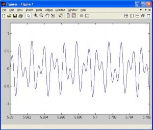
In mathematics a signal is a real function of a real variable f(t). In electronics it represents the evolution of a voltage (or a current) over the time and depends on the performances of the stage of the amplifier. Through a memory buffer, samples move to a digital-to-analog converter that produces a voltage signal, after an amplification stage that can limit the generation of the signal. A possible analysis consists of use Matlab with a PC sound card and an example of DTMF.
1. Introduction
Simplified diagram to generate an arbitrary signal v(t) from a digital format v(i) is shown in figure 1.
First of all, the information is available in digital format, inside a file in the vector numbers format (samples). Through a memory buffer, samples move to a digital-to-analog converter that produces a voltage signal to output to the external world, after an appropriate amplification stage. Shannon’s theorem states that the sampling frequency fs must satisfy the following relation: fs ≥ 2B, where B is the absolute band of the output signal. Even if the DAC can assure high sampling frequency, the absolute band of the signal that has to be generated depends on the performances of the output stage of the audio card. Because it’s designed for sound applications, it’s equipped with an amplifier with a 200Hz-20KHz bandwidth (in the ideal case). It must be also taken into account that the output signal will be distorted in amplitude and phase, more around the upper cutoff frequency. All that limits the generation of signals having with bandwidth lower than about 10KHz.
At this point, the most important issues are:
1- to generate a file with the signal in the digital format.
2- to setup a hw/sw sysytem able to perform the digital to analog conversion chain (DAC).
For More Details: Signal Generation with MATLAB. Example of DTMF in telephony

