Summary of Muxing Around With The CD74HC4067 + Arduino
This article explains how to expand the number of analog inputs on an Arduino using the CD74HC4067, a 16-channel analog multiplexer. By using just four digital pins to control the multiplexer, you can select one of 16 input channels to connect to a single analog pin, effectively reading multiple sensors with fewer microcontroller pins. The device acts as a 16-to-1 switch controlled by binary signals on the four select pins, and an enable pin can disable all channels. The tutorial includes wiring with potentiometers as sensor inputs and Arduino code to switch and read each channel.
Parts used in the CD74HC4067 Multiplexer Project:
- CD74HC4067 16-Channel Analog Multiplexer/Demultiplexer
- Arduino (or compatible microcontroller)
- 16 Potentiometers
- Connecting wires
- Breadboard (optional, for prototyping)
- 5V power supply (from Arduino)
The CD74HC4067 is a 16-Channel Analog Multiplexer/Demultiplexer. It is available in a breadboard-ready DIP package, or, if you are as addicted to breakout boards as I am, SparkFun offers a breakout board SSOP version. What it allows you to do is use 4 digital pins, to control the flow of one pin to 16 others. It can actually be used in either direction, and even with serial or other digital interfaces. For this tutorial we are just going to read the value from 16 pots because buying 16 analog sensors for this would have been overkill.
A multiplexer of this sort really just acts as a 16 to one 1 switch. The 4 digital pins are used to set HIGH or LOW, in a binary fashion (0-15) to determine what pin “SIG” is connected to. So bringing all 4 pins LOW would switch the CD74HC4067 to channel 0 (so SIG and C0 would be connected), bringing them all HIGH would switch it to 15 (so SIG and C15 would be connected). It is simple binary, but in the off chance you are one of the 99.8% of the world who doesn’t know binary, here is a simple table on the right.
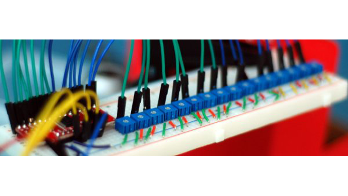
The schematic may seem complicated, but it is not. Not at all. And to prove it, look at the version on the left with out the pots; Much easier, right? The potentiometers are just connected with to ground and 5v, and the middle pin connected to one of the 16 channels on the CD74HC4067. 16 pots is just enough to make anything look scary little scary. Also of note is the EN, or enable, pin. The EN pin is a kill switch: pull it up to 5v to disable all channels, and ground it to enable them. Im just going to leave it at ground so we can use it and simplify things, but feel free to connect it to a digital pin, and control when the mux is enabled or disabled.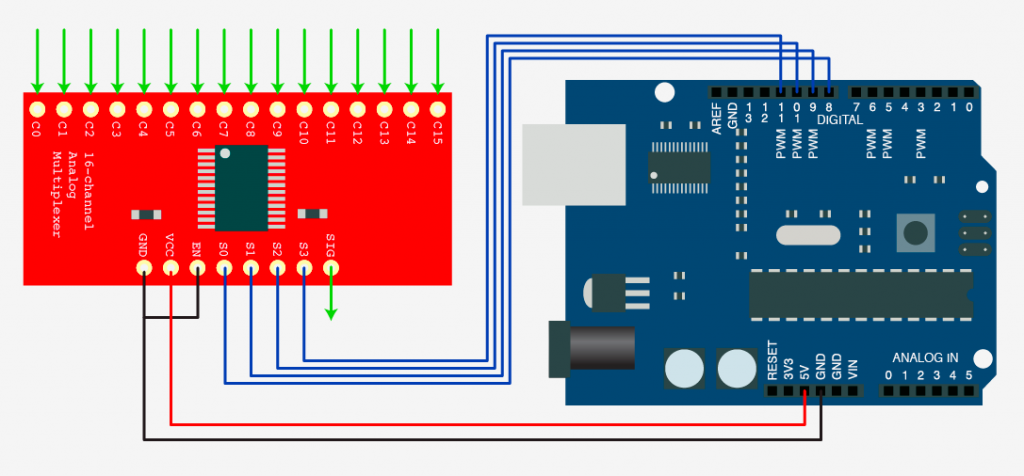
Nice and simple right?
For the code example I just took the binary table, made it into a simple array, and put it in a function that does this: You give the function a number 0-15. It looks up that number in the binary array, then it loops through those 4 numbers and sets S0, S1, S2, and S3 appropriately. (In the arduino software HIGH is the same as1 & LOW is the same as 0). After it sets the pins so that SIG is connected to the correct channel, it then reads analog 0 (where SIG is connected to) and returns that value. So all you need to do is something like this
For more detail: Muxing Around With The CD74HC4067 + Arduino