
Summary of Arduino-based Inductance Meter
This article describes an Arduino Uno shield designed to measure inductance, a feature often missing in standard digital multimeters. The device utilizes a Colpitts oscillator where the unknown coil creates resonance with known onboard capacitors. An Arduino measures this frequency to calculate inductance. A built-in 1uH inductor and push button enable calibration and limit maximum frequency, while a fast comparator converts the signal for processing.
Parts used in the Arduino-based Inductance Meter:
- Arduino Uno
- Inductance Shield
- Test leads
- 1uH inductance (onboard)
- Push button
- Two 1nF capacitors
- Microchip MCP6561R comparator
I’ve just finished a little Arduino project. It’s a shield for the Arduino Uno that lets you measure inductance. This is a functionality that I found missing in just about any digital multi meter. Yes, there are specialized LCR meters that let you measure inductance but they typically won’t measure voltages or currents. So I had to build my inductance meter myself.
The basic design is really simple. It a colpitts oscillator (http://en.wikipedia.org/wiki/Colpitts_oscillator) with the coil missing. You use the test leads to connect it to a coil which will make it resonate. The Arduino then measures the frequency at which the oscillator is resonating and calculates the inductance. The capacitors are part of the shield so the capacity is known.
There is 1uH of inductance included on the schield which is placed in series with the coil to be measured. This serves two purposes: The oscillator can resonate when you short-circuit the test leads. When you then press the push button on the shield, the software will use the current measurement as new calibration. It also puts an upper limit on the resonance frequency. This ensures that the software the rest of the circuit can keep up with the oscillator.
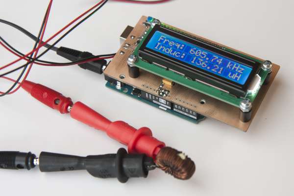
As can be seen from the schematic, the oscillator uses two 1nF capacitors in series. Together with the 1uH inductance, this limits the frequency to about 7.1MHz. In practice, it oscillates at around 5.4MHz when the test leads are short-circuited.
The oscillator output is followed by a comparator turning the sine wave of the oscillator into a square wave. I’ve used an inexpensive but fast Microchip MCP6561R. It has a maximum propagation delay of 80ns which allows it to keep up at the maximum frequency.
For more detail: Arduino-based Inductance Meter
- Why was this project built?
The author built it because standard digital multimeters lack inductance measurement capabilities. - How does the meter calculate inductance?
The Arduino measures the resonance frequency of a Colpitts oscillator connected to the test coil. - What is the purpose of the onboard 1uH inductance?
It allows the oscillator to resonate when leads are shorted for calibration and limits the maximum frequency. - Can I use this device to measure voltage or current?
No, this specific design focuses on inductance and does not measure voltages or currents like specialized LCR meters. - What component converts the sine wave to a square wave?
An inexpensive but fast Microchip MCP6561R comparator is used for this conversion. - What limits the oscillator frequency to about 7.1MHz?
The combination of two 1nF capacitors in series and the 1uH inductance limits the frequency. - How do you perform calibration on the shield?
You short-circuit the test leads and press the push button to set the current measurement as new calibration. - What happens when the test leads are open?
The oscillator cannot resonate, and the display shows the current calibration or zero-offset.