Summary of Momentary switch controls mains with latch-on and remote shutdown
This design replaces a latching mains power switch with a momentary button that latches via electronics. It provides debounce/protection against rapid toggling, separates manual control from power switching for higher current capability, ensures the switch stays off after power loss, and allows a unit to self-switch-off (optionally via an opto-thyristor). A capacitor/timer and SCR-based latching circuit with relay K1, transistors Q1/Q2, and diodes handle on/off sequencing and protection; LED and diode are embedded in the button for illumination and contact protection.
Parts used in the Momentary switch controls mains with latch-on and remote shutdown:
- Momentary control button BUT1 with normally open and normally closed contacts and embedded LED D7 and protection diode D8
- Relay K1 with contact pair SK1
- Capacitor C1
- Capacitor C2
- Diode D1
- Diode D2
- Diode D4
- Diode D6 (SCR)
- Optional opto-thyristor D11
- Transistor Q1
- Transistor Q2
- Resistor R1
- Resistor R2
- Resistor R4
The purpose of this Design Idea was to improve reliability, add new features, and replace a latching power switch with a momentary one.
The features are:
- The switch has foolproof protection against too frequent switching, which can be harmful for many applications.
- It can handle significant power because manual control and switching are separated.
- If an unexpected power outage occurs, the switch disconnects and remains off after power returns.
- A unit can switch itself off.
The control button BUT1 requires normally open and normally closed contacts, which must not be closed simultaneously.
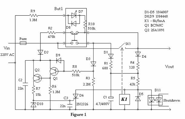
Initially, while the button is not pressed, the switch is opened because relay K1 is deactivated. The normally-open contacts of the relay and the button are the only components under voltage in this state.
When the button is actuated for the first time, the capacitor C1 is charged through D1 & R1, and relay K1 is activated, closing its contact pair SK1. The relay from now on is powered via D4 & R4 also.
When the button is released, the NC contacts allow C2 to charge to about one-half of the mains voltage through R2 & D2. This prepares the switch for subsequent shutdown when the button is pressed again. Q1 is on and Q2 is off.
With the next press of the button, both transistors change their state, and the discharge current of C2 triggers SCR D6, de-energizing the relay and disconnecting the load. Due to the latching action of the SCR, this state cannot be reversed by any subsequent actuation of the button while C1 is not discharged.
Releasing the button returns the circuit to its initial state.
LED D7 and protection diode D8 are embedded in the button. Modern LEDs are bright enough with a current is in range of 0.01 – 0.02mA, so despite the relatively high voltage, the total power consumption for the illumination is about 5 – 10mW or less.
An optional opto-thyristor D11 adds the ability for a powered system to be switched off from within the system.
Resistor R1 protects the button’s contacts from an inrush current. The constant R1C1 moderates the turn-on time.
For more detail: Momentary switch controls mains with latch-on and remote shutdown
- How does the circuit prevent too frequent switching?
The circuit uses timing components (R1 and C1, and the R1C1 time constant) and capacitor C2 charging behavior to provide foolproof protection against too frequent switching as described. - Can the unit switch itself off?
Yes, an optional opto-thyristor D11 provides the ability for a powered system to be switched off from within the system. - Does the switch stay off after an unexpected power outage?
Yes, if an unexpected power outage occurs the switch disconnects and remains off after power returns. - What happens when the button is first pressed?
On the first press capacitor C1 charges through D1 and R1, relay K1 activates and is then powered via D4 and R4, closing SK1 to latch on. - How is the relay deactivated on the next button press?
On the next press both transistors change state and the discharge current of C2 triggers SCR D6, de-energizing the relay and disconnecting the load. - Why must the button provide both NO and NC contacts?
BUT1 requires normally open and normally closed contacts so the circuit can charge C1 on a press and charge C2 via NC contacts after release to prepare for shutdown. - What protects the button contacts from inrush current?
Resistor R1 protects the button contacts from inrush current while the constant R1C1 moderates turn-on time. - How bright is the button illumination and what is its power consumption?
The embedded LED D7 is bright with a current of about 0.01 to 0.02 mA, giving total illumination power around 5 to 10 mW or less.