
Summary of Digital Book Cricket Game with ATtiny 85 using Arduino
This article details a DIY digital "Book Cricket" game using an ATtiny85 microcontroller, Arduino IDE, and a 16x2 LCD. The design minimizes pin usage by incorporating a HEF4094 shift register, allowing control via just two push buttons (Reset and Hit). Random numbers for gameplay are generated using the MCU's floating ADC input. The project offers a nostalgic, portable gaming experience with simple setup instructions and component lists.
Parts used in the Digital Book Cricket Game:
- Breadboard
- 16x2 LCD Display
- 7805 Voltage Regulator
- Push Buttons (2 units)
- 47K ohm Resistor
- 100 ohm Resistor
- 470 ohm Resistor
- HEF4094BP Shift Register
- ATtiny85V Microcontroller
- Arduino Software/IDE
The project described here is a digital implementation of “book cricket game” which Indian students normally use to play in their childhood time. The heart of the project is 8 bit MCU from AVR family called ATtiny85. ATtiny85 are small and cheap microcontrollers which are convenient for running simple programs with low footprint. The software used for programming the MCU is Ardunio which is a popular open source IDE.
Step 1: Design
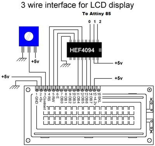
The overall design is kept to a least for simplicity and ease to use. The main components used in the circuitry are 16X2 LCD which is used to display the characters in 2 lines with maximum of 16 characters in one line, a serial in parallel out shift register HEF4094, ATtiny85, 2 push buttons and 7805 voltage regulator which regulates the voltage supply to maximum of 5 volts. Shift register HEF4094 is used because normally when LCD is used it requires 7 connections to the pins on the display. But if shift register is used the number of connections to the MCU can be reduced to only 3 wires.
Step 2: Circuit Diagram
Circuit Diagram for MCU connection with Shift Register.Pin 0,1,2 of ATtiny 85 goes to IC 4094 and pin 3(ADC) is kept floating.
Step 3: Working
For displaying the data on the LCD, arduino 3 wire LCD libraries are used because it provides an easy way to write the characters on LCD.
2 push switches are used to handle the input from the user. One is RESET switch which is used to reset the MCU and the other is HIT switch through which all the calibration and playing is done.
Components
1x Breadboard
1x 16*2 LCD
1x 7805 regulator
2x Push Button
1x 47K ohm
1x 100 ohm
1x 470 ohm
1x HEF4094BP
1x Attiny 85V
Step 4: STEPS TO PLAY THE GAME:
1. When the power switch is pressed, “Digital Book Cricket” will be displayed.
Step 5: STEPS TO PLAY THE GAME:
2. Using the HIT switch, number of wickets is set. Here a timer of 10 seconds is used to set the number of wickets. Also a timer of 10 seconds is used to set the number of over.
Step 6: STEPS TO PLAY THE GAME:
3. When all the basic set ups are over. Player 1 is supposed to bat first. He has to press the HIT button to score runs. He has to continuously press the HIT button until the innings are not over. At the end of the innings the scores are displayed on the screen.
1x Attiny 85V
Arduino
1x Breadboard
1x 16*2 LCD
1x 7805 regulator
For more detail: Digital Book Cricket Game with ATtiny 85 using Arduino
-
What is the core microcontroller used in this project?
The project uses an 8-bit AVR family microcontroller called ATtiny85. -
How does the circuit reduce the number of connections required for the LCD?
A serial in parallel out shift register HEF4094 reduces the necessary connections from 7 down to only 3 wires. -
How are random numbers generated for the game without external components?
Random numbers are generated by keeping the ADC channel floating to capture noise, then taking the mod 10 value to get integers from 0-9. -
What are the functions of the two push buttons provided?
One button acts as a RESET switch to reset the MCU, while the other is the HIT switch used for calibration and playing the game. -
Can the voltage supply be regulated to 5 volts in this design?
Yes, a 7805 voltage regulator is used to regulate the voltage supply to a maximum of 5 volts. -
What software is used to program the microcontroller?
The Arduino open source IDE is used for programming the ATtiny85 microcontroller. -
How long is the timer set for configuring wickets and overs?
A timer of 10 seconds is used to set both the number of wickets and the number of overs.
