
Summary of Arduino Knob
This article explains how to control an RC servo motor's position using an Arduino board and a potentiometer. The system reads the potentiometer's analog value, scales it to a 0-180 degree range, and uses the Servo library to adjust the motor accordingly.
Parts used in the Arduino Knob:
- Arduino Board
- Servo Motor
- Potentiometer
- Hook-up wire
Control the position of a RC (hobby) servo motor with your Arduino and a potentiometer.
This example makes use of the Arduino servo library.
Hardware Required
- Arduino Board
- (1) Servo Motor
- (1) Potentiometer
- hook-up wire
Circuit
Servo motors have three wires: power, ground, and signal. The power wire is typically red, and should be connected to the 5V pin on the Arduino board. The ground wire is typically black or brown and should be connected to a ground pin on the Arduino board. The signal pin is typically yellow or orange and should be connected to pin 9 on the Arduino board.
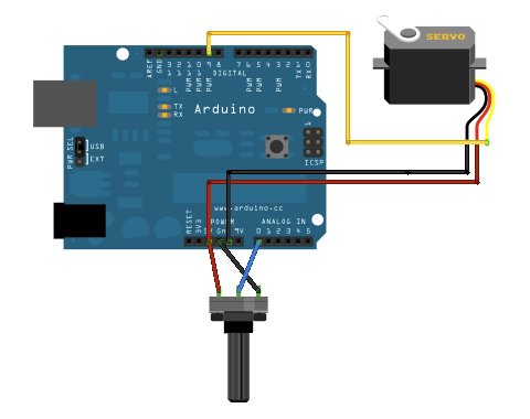
The potentiometer should be wired so that its two outer pins are connected to power (+5V) and ground, and its middle pin is connected to analog input 0 on the Arduino.
Schematic

Code
// Controlling a servo position using a potentiometer (variable resistor)
// by Michal Rinott <http://people.interaction-ivrea.it/m.rinott>
#include <Servo.h>Servo myservo;  // create servo object to control a servoint potpin = 0;  // analog pin used to connect the potentiometer
int val;    // variable to read the value from the analog pinvoid setup()
{
myservo.attach(9);  // attaches the servo on pin 9 to the servo object
}void loop()
{
val = analogRead(potpin);            // reads the value of the potentiometer (value between 0 and 1023)
val = map(val, 0, 1023, 0, 179);     // scale it to use it with the servo (value between 0 and 180)
myservo.write(val);                  // sets the servo position according to the scaled value
delay(15);                           // waits for the servo to get there
}
For more detail: Arduino Knob
- Which library is required for this project?
The example makes use of the Arduino servo library. - What color wires are typically used for power and ground on a servo motor?
The power wire is typically red, and the ground wire is typically black or brown. - Which pin should the servo signal wire connect to?
The signal pin should be connected to pin 9 on the Arduino board. - How is the potentiometer wired to the Arduino?
The two outer pins connect to power (+5V) and ground, while the middle pin connects to analog input 0. - What value range does the analogRead function return?
The value read from the analog pin is between 0 and 1023. - Why is the map function used in the code?
The map function scales the value from 0-1023 to use with the servo, resulting in a value between 0 and 180. - What is the purpose of the delay(15) command?
The delay waits for the servo to get to the desired position before reading the next value.