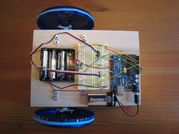
The purpose of this project is to design and build a simple light-following robot using an Arduino Duemilanove microcontroller board. I really wanted to share a robot project that was cheap, simple to build, and had a complete set of instructions for all of the different steps. I hope I’ve succeeded and I’d love to get comments about making this instructable even better.
The design of this robot focused around using the book “Getting Started with Arduino” by Massimo Banzi and published with [makezine.com Make]. I also employed code for running the servos from a project titled: How to Make an Arduino Controlled Servo Robot (SERB).
The Arduino Mothbot is in total a pretty quick robot to build. Assuming you start with all of the parts and don’t have to improvise, the project in total should take maybe an hour to build. That is if you follow the instructions and copy the code. However, if you build only one feature at a time and test along the way then this project could take significantly longer. The advantage of the longer track is that you’ll probably learn a lot more and have some fun along the way.
 Step 1: Gather your Parts and Tools
Building this robot is going to cost you roughly $80 in parts if you’ve never done anything like this before. The cost for me was significantly less since I’ve got a lot of electronics lying around to work from. However, I know how frustrating it can be to try and follow an instructable without knowing which parts to get, where to order from, and how much everything will cost up front so I’ve done all that work for you. Once you’ve got the parts all squared away it should be a snap to do this project. Follow the following link to my project wiki to get a complete parts list.
Now you may want to get some tools. Since this project employs a solderless breadboard you can do without a lot of fancy electronics equipment. Hopefully you can find the rest of the things you need in a garage:
1. Needle nose pliers
2. Wire Cutters
3. Flat head screw driver
4. Small Phillips (4-sided) screw driver
5. Adjustable wrench or 11/32″ hex wrench
6. Drill
7. 1/16″, 5/32″ and 7/32″ drill bits
8. Saw (optional)
9. Safety Goggles
Please use safe practices when using any power tools.
Step 2: The Planning Stage
Before I started this project I looked around Instructables at a lot of other projects. I also spent some time reading the book “Getting Started with Arduino” by Massimo Banzi. Nearly everything in this project is done from an example on this website or in the book. I designed the project this way in an attempt to make it accessible to the novice roboticist.
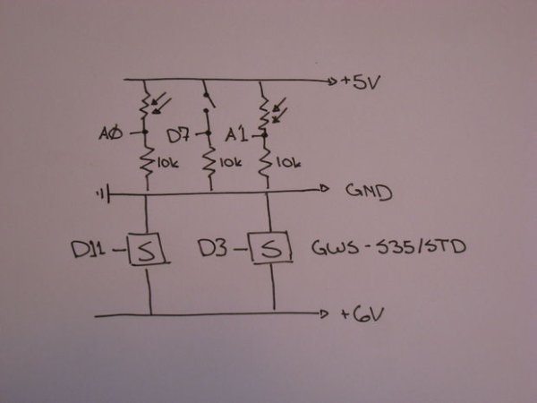
In my planning phase I did not only looked at hardware and coding but did my electronics homework as well. I wanted to draw up a simple electronics schematic for this project so I could follow what was going on as I built it. You can see in the picture the different components, power lines, and the Arduino pins. Hopefully it’s a clear diagram and also illustrates how simple the electronics for this project is.
Step 3: Connecting the Servos to the Arduino
If you’re going to build a robot the first thing you probably want to work out is how to get it moving around. Most likely you want to be able to send it forward, backward, right, left and make it stop. If you can’t figure out how to command it to move properly you’re not likely to be able to make it do anything when you connect all the sensors. Below are the steps to connect the motor to the Arduino.
1. The first thing to do when setting up the solderless breadboard is to set up the ground (GND) and power (+6V) for the servos. I chose to use the two long strips on the board that would be closest to the Arduino.
2. Once the ground and power lines are identified connect the ground of the Arduino board to the ground strip on the solderless breadboard. Do not connect the power to the solderless breadboard yet.
3. Each servo has three wires that come out of them. Mine have a black, red, and white wire for each. The black is for ground, the red is for power, and the white is the control wire. Cut three jumper wires for each servo of the same size (so 6 in total)
4. Attach the jumper wires to the end of the servo wires and then each servo to the solderless breadboard.
5. Now use jumpers to connect the ground and power from each servo to the ground and power of the solderless breadboard.
6. Now connect the control wires from each servo to the Arduino. Connect the left servo to digital output (PWM) 3 and the right servo to digital output (PWM) 11.
7. Finally, connect the ground and power from the 4AA batteries to the solderless breadboard ground and power. Don’t be alarmed if the servos start moving when your Arduino has no power or is not yet programed.
8. Using the code you should now be able to run the motors in the forward, backward, left or right directions using the included functions.
Step 4: Testing out the Motors
I think it’s important to include some of the test code I used when putting together the Arduino Mothbot. If you’re interested and willing to put in the time to tinker around I think you’ll find these code snippets educational and useful in other projects.
Before I post any code below I want to make it known that the following is based on another great project called How to Make an Arduino Controlled Servo Robot (SERB). I learned a lot from following the work on that instructable and want to give credit where it is due.
Step 5: Integrating the On/Off Button
Now you may be wanting to turn your robot on and off with the push of a button. The Arduino itself will run code in an endless loop until you unplug it, which can be quite frustrating when you plug in your robot on the table and it starts running away from you! Integrating the button is a great step in this process because you’ll also learn how to use buttons for other things, like creating a bumper to detect when the robot hits a wall.
As a note, you’ll notice I removed the servos from the solderless breadboard for most of my pictures. This just helps make the image more clear when I’m showing different steps.
1. To begin, disconnect power from the servo motors before doing any more work. Remember to do this every time you add something to this project.
2. Now you may want to be able to turn your robot on and off as opposed to having the robot immediately start moving when you connect the power.
3. Identify a strip on the opposite side of the solderless breadboard to be power for on/off button (and later the sensors).
4. Using a long jumper wire connect the power (+5V) from the Arduino to the strip you just identified.
5. Connect two jumper wires to the momentary switch and plug one end into the (+5V) power
6. Plug the other end of the momentary switch into a smaller strip in the middle of the solderless breadboard.
7. From that same strip connect a 10K ohm resistor to the strip and the other end into ground
8. Finally, connect a wire from the strip with the switch and the resistor on one end and place the other end in digital input 7 on the Arduino.
9. Now, with the code you should be able to use the button to turn on and off the robot. If you use the code with the LED (digital output 13) you will see the on-board LED turn on and off with the robot. This is a great way to test the Arduino code if you have the power to the motors disconnected.
 Step 6: Testing the On/Off Button
This new code includes the information for using the On/Off button and making the onboard LED blink
Step 7: Integrating the Light Sensors
What would an Arduino Mothbot be if it didn’t have light sensors? The point of this simple project is to make a robot that is attracted to the brightest light. For this we’ll need to integrate some light sensors, also known as photo-resistors.
1. Again, disconnect the power from the servo motors before doing this step
2. The setup for the light sensors will be done twice. It is almost the exact same setup as the momentary switch. Actually, it is the same setup, but this time you will use the light sensor (photo-resistor) instead of a momentary switch.
3. Because this robot will use the two light sensors to pick a direction to drive it is recommended that you set up each light sensor on opposite sides of the solderless breadboard or as far apart as possible.
4. Connect one end of a light sensor to the (+5V) power line and the other end into a small strip in the center of the board.
5. Connect a 10k ohm resistor to that same strip and the other end to ground
6. Now connect a jumper wire from the small strip (where the photo resistor and regular resistor are connected) and plug the other end into an analog input.
7. Connect the left sensor to analog input 0 on the Arduino and the right sensor to analog input 1.
8. You should now be able to use the light sensors to move the servos.
For more detail: The Arduino Mothbot


