
Summary of Simple Distance Measuring Device
This project shows how to wire an HC-SR04 ultrasonic sensor to an Arduino UNO and 16x2 LCD to measure distance, with a potentiometer for LCD contrast and a 9V battery powering the Arduino. It lists required parts and provides pin connections for the sensor, LCD, potentiometer, and power to display measured distances.
Parts used in the HC-SR04 Distance Measuring Project:
- HC-SR04 PING ultrasonic sensor (x1)
- Arduino UNO (x1)
- LCD 16x2 (x1)
- 9V battery + DC adapter (x1)
- Potentiometer 10kΩ (x1)
- Set of jumper wires
In this project we are going to learn how to use the HC-SR04 PING))) ultrasonic sensor to measure distance. This sensor is also often used on robots to detect obstacles.
Difficulty level: Easy
Time needed: ±10 minutes
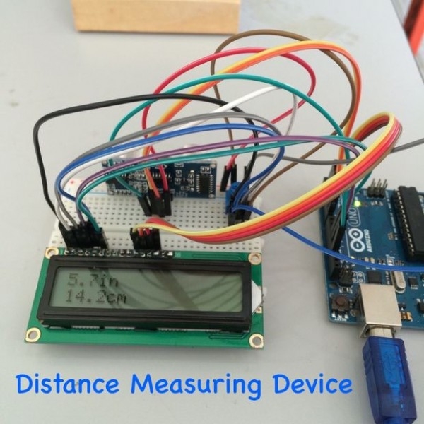
Step 1: Things You’ll Need
HC-SR04 PING sensor (x1)
Arduino UNO (x1)
LCD 16×2 (x1)
9V battery + dc adaptor (x1)
Potentiometer 10kΩ (x1)
Set of jumper wires
Step 2: Plug the PING sensor and LCD
HC-SR04
GND (pin 1) to potentiometer (left pin)
VCC (pin 2) to potentiometer (right pin)
VO (pin 3) to potentiometer (center pin)
RS (pin 4) to arduino digital pin 12
RW (pin 5) to potentiometer (left pin)
E (pin 6) to arduino digital pin 11
D4 (pin 11) to arduino digital pin 5
D5 (pin 12) to arduino digital pin 4
D6 (pin 13) to arduino digital pin 3
D7 (pin 14) to arduino digital pin 2
Potentiometer
left pin to arduino GND
right pin ro arduino 5V
PING Sensor
VCC to arduino 5V
Trig to arduino digital pin 7
Echo to arduino digital pin 6
9V battery
To arduino DC power socket
For more detail: Simple Distance Measuring Device
- What components are needed for this HC-SR04 distance measuring project?
HC-SR04 PING sensor, Arduino UNO, LCD 16x2, 9V battery with DC adapter, 10kΩ potentiometer, and jumper wires. - How is the HC-SR04 powered in the project?
VCC of the PING sensor is connected to Arduino 5V and GND to Arduino GND. - Which Arduino pins connect to the HC-SR04 trigger and echo?
Trig connects to Arduino digital pin 7 and Echo connects to Arduino digital pin 6. - How do you wire the 16x2 LCD to the Arduino?
RS to digital pin 12, E to digital pin 11, D4 to digital pin 5, D5 to digital pin 4, D6 to digital pin 3, D7 to digital pin 2. - How is the potentiometer connected for LCD contrast?
Potentiometer left pin to Arduino GND, right pin to Arduino 5V, and center pin (VO) to LCD VO; potentiometer left pin also connects to LCD RW and GND as listed. - How is the Arduino powered in this setup?
The 9V battery with DC adapter is connected to the Arduino DC power socket. - Does the project include instructions for adjusting LCD contrast?
Yes; the potentiometer center pin is wired to VO on the LCD so adjusting the potentiometer sets the contrast. - Can this sensor setup be used for obstacle detection on robots?
Yes; the article notes the HC-SR04 is often used on robots to detect obstacles.
