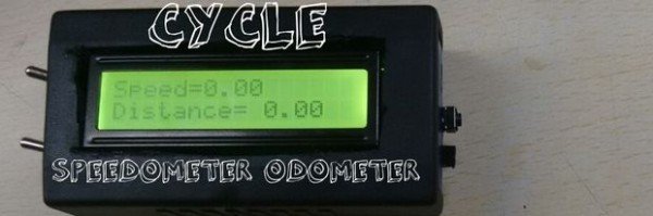
Summary of DIY SPEEDOMETER AND ODOMETER
This project builds a bicycle speedometer/odometer using an Arduino, reed (magnetic) switch and magnet on a spoke, and a 16x2 LCD. The reed switch signals wheel rotations to the Arduino, which computes distance from wheel diameter and velocity from time, then displays results; a momentary button cycles modes and basic enclosure and waterproofing complete the device.
Parts used in the DIY SPEEDOMETER AND ODOMETER:
- Arduino board (Pro Mini, Uno, or Micro)
- Arduino 16x2 LCD
- 7805 voltage regulator (optional)
- Two switches for backlight and on/off (optional)
- 220 ohm resistor
- 10k ohm trimmer potentiometer
- Female and male headers (optional, for detachable reed switch)
- Reed switch (magnetic switch)
- Wire
- Momentary switch (to change modes)
- 0.1 uF capacitor
- 10k ohm resistor (pull-down)
- Soldering iron
- Solder
- Enclosure (plastic or wooden)
- Cutting tool (e.g., Dremel)
- Hot glue or adhesive
Step 1: HOW IT WORKS
The operation of a project is uncomplicated. Understanding it is crucial for project development. Essentially, the device includes a reed switch or magnetic switch attached to the bicycle frame and a magnet attached to one of the spokes. The magnet activates the switch with each turn of the wheel. The arduino receives the signal, counts the rotations, and calculates the distance covered based on the pre-entered diameter of your cycle. The arduino also keeps track of the time and computes the velocity. The information is sent from the Arduino to the LCD display where it is presented in miles per hour (conversion is optional).
Step 2: MATERIALS REQUIRED
The full project would cost you about 5$-10$ depending on the place you live in. The cycle speedometer also would require moderate soldering skills and an afternoon. so without any further ado the materials for the build are –:
1. The arduino board – i got Rs.330 which is around 5$ but to programme the pro mini you will also need to have an arduino uno or an usb to ttl adapter (how to program an arduino pro mini with an uno) or if you don’t have it then use an arduino micro or an arduino uno.
2.Arduino 16×2 lcd (Rs150 or 2.3 $)
3.7805 voltage regulator (increases the control over the contrast no major difference -optional)
4. 2x switches for backlight and on off (optional)
5.220 ohm resistor
6. trimer pot 10k ohm
7.female headers and male headers if you want the reed switch to be detachable
8. reed switch
9.wire
10. a momentary switch to change the modes
11. 0.1uf capacitor to reduce the debounce of the button
12.10k ohm resistor
The tools you would require are
1. soldering iron
2.solder
3. enclosure
4. cutting tool like the dremel to cut out holes in the enclosure to mount he lcd and stuff
5. hot glue or any adhesive to mount the various components.
Step 3: THE CODE
It’s a good idea to upload the code before working on the electronics to avoid a tangled mess of wires later on.
Upload the provided code to the Arduino, but remember to adjust the size of your bike’s wheels.
Step 4: THE ELECTRONICS
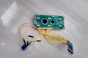
The wiring diagram can be found above also I have mentioned it down
LCD -ARDUINO
1 – GND
2 VCC
3 VIPER PIN OF THE POT (ends to vcc and gnd and center to pin 3 of lcd)
4 13
5 gnd
6 12
7 —
8 —
9 —
10 —
11 11
12 10
13 9
14 8
15 VCC
16 GND
Also
a 220 ohm resistor is to be connected between pin 2 of the arduino and ground(pull down)
the momentary switch is connected to pin two and vcc
a 0.1 uf capacitor between the two terminals of the switch to reduce the debounce
the reed switch to vcc and A0
a resistor between A0 and gnd (pull down)
After connecting all this the wiring would be complete and now you can connect power and check if every thing is working
Step 5: THE ENCLOSURE

The casing could either be a plastic container or a wooden one, as long as it is durable and spacious enough.
After installing the switches, LCD, button, and headers, make sure to test the functionality of the device as well.
Make the cycle as waterproof as you can, since it will face the harshest conditions.
Step 6: TESTING AND TROUBLESHOOTING
Connect a 9v battery and test all three modes completely. Bring a magnet close to the reed switch and the speed and distance should increase.
If it is not so in your case then post your doubts and queries in the comments and i will answer them back as soon as possible…
Source: DIY SPEEDOMETER AND ODOMETER
- How does the speedometer detect wheel rotations?
The magnet on a spoke activates the reed switch each wheel turn and the Arduino counts these signals. - How is distance calculated?
The Arduino uses the counted rotations and the pre-entered wheel diameter to calculate distance. - How is velocity computed?
The Arduino tracks time between pulses and computes velocity from rotation rate and wheel diameter. - Can the display show miles per hour?
Yes; the LCD presents speed in miles per hour and conversion is optional. - What components are connected to the LCD pins?
The article lists connections from LCD pins to Arduino pins including power, pot for contrast, and data pins 8–13 mapped to LCD pins 8–14 and others as specified. - How is switch debounce handled?
A 0.1 uF capacitor is placed across the momentary switch to reduce debounce. - What power source is suggested for testing?
A 9V battery is used in testing to check modes and functionality. - Is soldering required for this project?
Yes; moderate soldering skills are required to assemble the electronics. - How should the reed switch and magnet be mounted?
The reed switch is attached to the bicycle frame and the magnet to a spoke so the magnet passes the switch each rotation. - Do I need to upload code before wiring?
Yes; the article advises uploading the Arduino code first and adjusting the wheel size before assembling electronics.