
Summary of RFID with Arduino
This tutorial demonstrates integrating an RDM630 RFID module with an Arduino using the NewSoftSerial library. The project reads 14-byte data packets containing a start byte, a 10-byte ASCII ID, a 2-byte checksum, and an end byte. It validates the data by comparing the transmitted checksum against a calculated XOR value of the ID blocks to ensure integrity.
Parts used in the RFID with Arduino Project:
- RDM630 UART module
- Antenna
- Breadboard
- LED
- Arduino board
- NewSoftSerial library
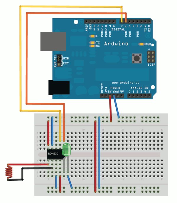
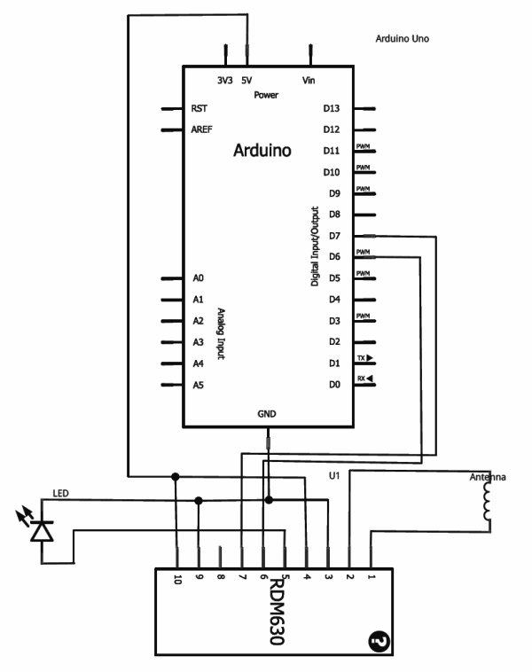
If you ever wanted to integrate RFID functionality into your project, this small tutorial might help you accomplish that. I used the RDM630 module from seeedstudio in its UART version. It comes on a small board with presoldered connectors which fits perfectly on a breadboard. You only need to connect the antenna to the two pin socket. You also can connect a LED to indicate if the antenna picks up a signal. The signal output can be easily read by using theNewSoftSerial library and assigning the RX TX ports.
The signal readings are transmitted in byte blocks. The first byte (02) is the start of text byte in HEX-ASCII format. Then following is the 10 byte data for the ID which has been recognized. After that a 2 byte checksum is transmitted. Followed by the last byte (03).
To translate the 10 byte HEX-ASCII data to the unique ID, you only have to map the bytes to the according ASCII character. For details have a look into the datasheet.
This is an example code which checks if the data was received correctly. It prints the ID and checks if the transmitted checksum is equal to the calculated checksum of the ID.
#include “NewSoftSerial.h”
#define stx 2
#define etx 3NewSoftSerial mySerial(6, 7);
int counter;
byte data[14];
byte hexBlock1,hexBlock2,hexBlock3,hexBlock4,hexBlock5;
byte hexCalculatedChecksum,hexChecksum;void setup() {
Serial.begin(9600);
mySerial.begin(9600);
}void loop() {
if (mySerial.available() > 0) {
data[counter] = mySerial.read();
counter++;
if(counter > 13) {
//we read the whole message, so reset counter
counter = 0;
//check if start of text and end of text is correct
if(data[0] == stx && data[13] == etx) {
Serial.println(“Start of text and end of text correctly received.”);
Serial.print(“ID: “);
//show ID
for(int x = 1; x < 11; x++) {
Serial.print(data[x], BYTE);
}
Serial.println(“”);
Serial.print(“Checksum: “);
//show checksum
Serial.print(data[11], BYTE);
Serial.println(data[12], BYTE);//Hex ID blocks. Two transmitted Bytes form one Hex ID block.
//Hex ID blocks: 6 2 | E 3 | 0 8 | 6 C | E D
//Transmitted Bytes: 36H 32H | 45H 33H | 30H 38H | 36H 43H | 45H 44H
hexBlock1 = AsciiCharToNum(data[1])*16 + AsciiCharToNum(data[2]);
hexBlock2 = AsciiCharToNum(data[3])*16 + AsciiCharToNum(data[4]);
hexBlock3 = AsciiCharToNum(data[5])*16 + AsciiCharToNum(data[6]);
hexBlock4 = AsciiCharToNum(data[7])*16 + AsciiCharToNum(data[8]);
hexBlock5 = AsciiCharToNum(data[9])*16 + AsciiCharToNum(data[10]);//Transmitted checksum.
hexChecksum = AsciiCharToNum(data[11])*16 + AsciiCharToNum(data[12]);//XOR algorithm to calculate checksum of ID blocks.
hexCalculatedChecksum = hexBlock1 ^ hexBlock2 ^ hexBlock3 ^ hexBlock4 ^ hexBlock5;
if ( hexCalculatedChecksum == hexChecksum )
{
Serial.println(“Calculated checksum matched transmitted checksum.”);
}
else {
Serial.println(“Calculated checksum didn’t match transmitted checksum. Corrupt data!”);
}
}
}
}
}uint8_t AsciiCharToNum(byte data) {
//First substract 48 to convert the char representation
//of a number to an actual number.
data -= ‘0’;
//If it is greater than 9, we have a Hex character A-F.
//Substract 7 to get the numeral representation.
if (data > 9)
data -= 7;
return data;
}
An example reading would look like this:
Start of text and end of text correctly received.
ID: 4200442C01
Checksum: 2B
Calculated checksum matched transmitted checksum.
Here is a demonstration of the RFID reader in action:
For more detail: RFID with Arduino
- How do I connect the antenna to the RDM630 module?
You only need to connect the antenna to the two pin socket on the small board. - Can I use an LED to indicate signal detection?
Yes, you can connect an LED to indicate if the antenna picks up a signal. - What library is required to read the signal output?
The NewSoftSerial library is used to easily read the signal output by assigning RX TX ports. - What is the structure of the signal transmission?
The signal is transmitted in byte blocks consisting of a start byte, 10 bytes of ID data, 2 bytes of checksum, and an end byte. - How do I translate the HEX-ASCII data to a unique ID?
You must map the 10 bytes to the according ASCII character as detailed in the datasheet. - Does the code verify data integrity?
Yes, the example code checks if the transmitted checksum equals the calculated checksum of the ID blocks. - What algorithm calculates the checksum in the provided code?
An XOR algorithm is used to calculate the checksum from the five hex ID blocks. - What happens if the calculated checksum does not match?
The system prints a message stating that the calculated checksum did not match the transmitted checksum, indicating corrupt data.