
Summary of GSM Remote Control – GSM Module
This article details a modular GSM remote control system designed for applications like gate and temperature control. The core innovation is a detachable auxiliary board housing the mobile phone, allowing easy module replacement or dual-module support (SIM900 or M10) without redesigning the main circuit board. The system uses specific pin strips for power and communication, with firmware managing reset procedures uniformly across both supported modules by controlling power cycles via the PWR line.
Parts used in the GSM Remote Control:
- GSM Mobile Phone
- Small auxiliary printed circuit board
- Main printed circuit board
- Connector
- PIN strips (3-pin and 16-pin)
- SIM900 module (SIMCom)
- M10 module (Quectel)
- Microcontroller
- Firmware
- Transistor T2
- Vcc line
- PWR line
- VDD_EXT line
This GSM Mobile is used for our Remote Control (for example Gate Control, Temperature Control….). We use the word ‘module’ because, unlike what we did in our remote control projects, this time around the mobile phone is not mounted on a printed board, but rather on a small auxiliary board which is then inserted in a connector specifically created on the main printed board; though this alternative may seem rather complex at first blush, it does have two advantages: the first is that if the GSM module should stop working, and you should not be able to find the same model, you can simply replace it with a different module without having to replace the entire circuit board.
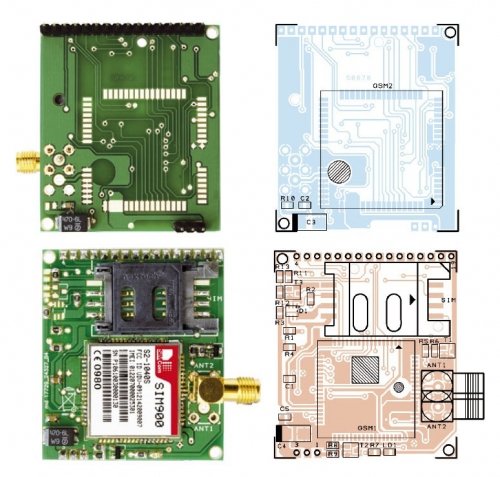
All you need to do is create a small board compatible with your unit, with the pin strips arranged as required by the circuit board. The second advantage is that the module’s printed board is double-faced and can thus host a GSM module on one face and a different one on the other. This provides the option of choosing between two different mobile phones according to one’s needs.
The GSM module
Let us begin by describing the module hosting the mobile phone: it is a printed circuit board measuring about 1.75×1.95 inches, with two pin strips (a 3-pin one and a 16-pin one) used to connect with the circuit board of the remote control device; the first pin strip carries digital power (both positive and negative), in addition to the ignition control line (PWR), while the second strip contains all the communication signals and lines to and from the GSM module, as well as the analogical section of the phones (AGND, contact 11). This pinout remains unchanged regardless of which of the two modules (SIM900 from SIMCom or M10 from Quectel) is in use.
Let’s now take a look at the electrical scheme, which displays the connections for both modules; recall that either GSM1 or GSM2 will be used. The two components have more or less the same command lines, so the relative pins can be connected together with the pin-strip contacts. The main differences between the two modules are found in their reset properties. SIM900 is equipped with a specific reset line, while in the case of M10 it is necessary to turn the power off and short-circuit the VDD_EXT line. In reality, in order to simplify things, the microcontroller’s firmware handles both GSM modules in the same way: in order to reset them, it turns off the main power supply and short-circuits the abovementioned line for just a second.
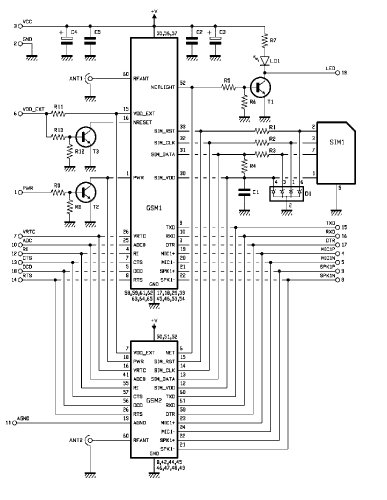
How is power handled? The PWR line is needed by the microcontroller to turn the GSM module on and off. The modules that are used are constantly under tension, provided by the Vcc line to pins 55, 56, 57 for SIM900 and to pins 50, 51, 52 in the case of M10; these modules are turned on or off according to the logical level applied to their PWR line (pin 1 of GSM1 or pin 18 of GSM2) . The PWR line is equipped with an internal pull-up resistance and is active at logical zero; therefore, in order to switch the cellular module on, the microcontroller sets PWR at a high logical level (contact 1 of the pin-strip) and causes transistor T2 to saturate; this transistor will then sets the PWR line for both GSM1 and GSM2 at a low level.
For more detail: GSM Remote Control – GSM Module
-
Why use a separate auxiliary board for the GSM module?
It allows replacing a failed module with a different model without changing the entire circuit board and enables hosting two different modules on a double-faced board. -
Which two GSM modules are compatible with this design?
The design supports the SIM900 from SIMCom and the M10 from Quectel. -
How does the system handle the reset difference between the two modules?
The microcontroller firmware simplifies this by turning off the main power supply and short-circuiting the VDD_EXT line for just a second for both modules. -
What is the function of the PWR line?
The PWR line is used by the microcontroller to turn the GSM module on and off based on its logical level. -
How is the cellular module physically switched on?
The microcontroller sets the PWR line to a high logical level, causing transistor T2 to saturate and set the PWR line to a low level. -
Are the pinouts identical for both the SIM900 and M10 modules?
Yes, the pinout remains unchanged regardless of which of the two modules is in use. -
What components carry digital power and ignition control?
The first pin strip carries digital power (positive and negative) and the ignition control line (PWR).
