
Open-source hardware? Arduino(tm) is the first name to come to mind! As great as it is, sometimes we need a small microcontroller solution for a project, or a stripped-down version for cost-effectiveness.
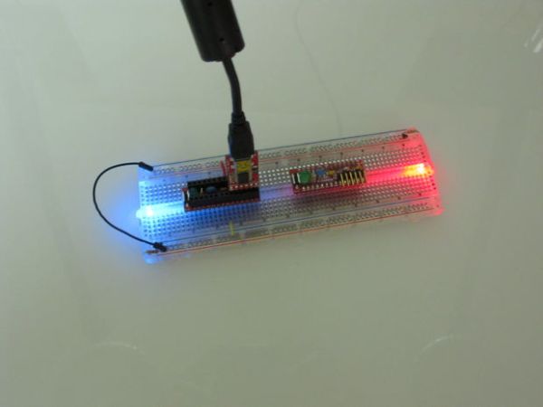
The Ardweeny is the solution. These small kits are 100% compatible with the Arduino programming environment, are very small, (and unlike the regular Arduino) they can fit on a breadboard. Oh, and they’re quite inexpensive too!
In the regular configuration, you build the backpack, and have it sit on top of the IC, soldering the leads to the legs of the Atmel microcontroller. Although convenient, it exposes the legs to unwanted bending.
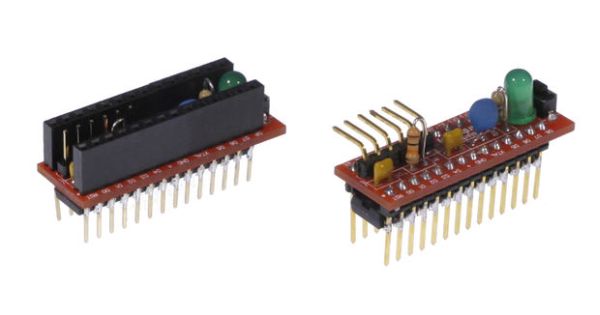
This Instructable by Solarbotics Intern Rudy Bernard shows how you can build your Ardweeny with stiffer extra-long socket-headers that protect the fragile microcontroller legs and the topside programming pins.
Step 1: Parts You’ll Need
Electronic Parts
– Ardweeny kit (Solarbotics part # : KARDW)
– 2x 6-Pin Header (HVWTech part #: FPin6L-413 )
– 2x 8-Pin Header (HVWTech part #: FPin8L-413 )
Tools Required
– Soldering equipment (soldering iron / solder / cleaning sponge) (HVW tech soldering tools )
– A pair of Needle-nose pliers (HVWTech part #: 43060 or 43061)
– A pair of Flush Cutters (HVWTech part #: 43040 )
– Safety Glasses – VERY important when clipping and snipping! (Solarbotics part #: 5330)
Step 2: Soldering of the capacitors
Start with the 0.01uF capacitors. They aren’t polarized so you can position them in the way you want as long as you put one each into rectangle C1 and C2.
Snug them down, solder them in, and trim off the excess leads poking out from the bottom of the PCB.
Step 3: Soldering of the resistors
You have 2 resistors with different values, so you will have to take care with them.
Let’s start with the resistor R1 – 10k (brown / black / orange / gold). Bend it over with a pair of needle-nose pliers like the picture below and put it in the R1 rectangle. Solder it in place, and snip off the excess lead underneath
Do the same thing with the R2 – 470 ohm (yellow / purple / brown / gold).
Step 4: Soldering of the Resonator and LED
Put the 3-lead resonator in the “Xtl” rectangle. It is not polarity sensitive, so which-way-around does not matter. Solder and snip, like with the resistors & capacitors.
However the LED have a polarity so you will have to take care which way it is installed.Take a close look at it and find the flat side of the LED. The flat side is the cathode, which also has the shorter leg of the two (the other, longer lead is the anode). The flat-side goes to the square pad on pcb. You can also see a flat side on the silk screen.
The push button is the reset switch of the Arweeny. This one is very simple to soldering. Stick it in and solder it down!
The header is use to program the Ardweeny. You can help yourself by using masking tape to hold it in place. Try to solder one leg first and look on the top if the header is sitting straight up and down, and in all the 6 holes. If not, you only have to heat one header and move the header at the right place.
For more detail: The Ardweeny: the little friend of the Arduino (and how to beef it up)