Summary of PUPPET CONTROLLER using arduino
This project builds a puppet controller combining human input, mechanical servos, and computer animation using an Arduino, flex sensor (or potentiometer), and Processing for on-screen animation. It covers wiring servos and a sensor, Arduino servo code with serial output, replacing the pot with a flex sensor and adjusting mappings, creating a simple mouth animation in Processing, and linking physical input to virtual animation. Mounting and testing complete the setup.
Parts used in the Puppet Controller:
- Arduino board (Uno or similar)
- Screw shield (optional)
- 2 servo motors
- Potentiometer (0 to 100Kohm) or flex sensor
- 100K resistor
- Jumper wires
- Breadboard (implied)
- USB cable (for Arduino serial/USB)
- 9V battery connector (optional starter kit item)
- Pipe cleaners (for show)
- Computer running Processing (processing.org)
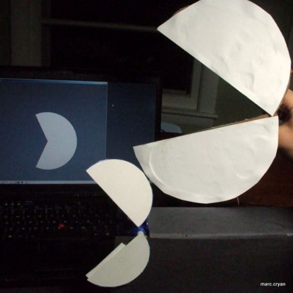
Three kinds of motion: Human, Mechanical, Animation. Blend them together to build a puppet controller for the real and virtual world.
Or, Pacman – three ways.
This Instructable includes:
– Using an adjustable resistor as input to the Arduino Micro-controller
– Controlling two servo motors from the Arduino
-Controlling animation on the computer from the Arduino
Here are the basic steps:
– Servo control with Arduino and potentiometer
– Replace potentiometer with a flexible sensor
– Create animation on the computer screen
– Setup communication between the computer and Arduino
– Mount everything in a usable way and test it out!
Here is a good book for learning arduino:
Programming Arduino Getting Started with Sketches
Here is an arduino starter kit on amazon:
Starter Kit for Newsite Uno R3 – Bundle of 6 Items: Newsite Uno R3, Breadboard, Holder, Jumper Wires, USB Cable and 9V Battery Connector
Step 1: Servo Code for Arduino
Basic setup to controll a motor with Arduino based on input from a sensor.
Parts:
2 servo motors
Arduino board ( i have a screw shield on it, but that is not critical)
Potentiometer (this one is 0 to 100Kohm)
Jumper wires
Pipe cleaners (for show).
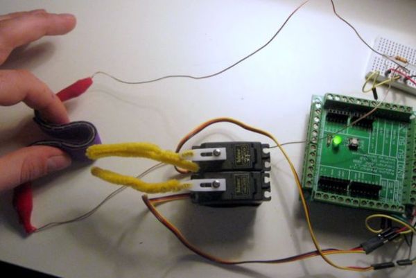
1 – Wire the servo motors. These are special motors, you can input an angle and the motor will do it. The servos have three wires: Power (red, 5V) – Ground (black) – Yellow (communication – angle info goes in here).
In this setup: Red goes the Arduino 5V, Black goes to Arduino Ground, Yellow will go to specific input/ouput pins on the Arduino.
Servo 1: Yellow —– Pin 9
Servo 2: Yellow —–pin 10
2 – Wire the potentiometer
This has three leads.
Lead 1 —– 5V
Lead 2 —– Pin 0
Lead 3 —— Ground
3 – Code –
The code below is from the Arduino example for servo motor control. It includes the servo library, which makes it easy to communicate to the servo.
This also maps (scales) the input from the pot into an angle (in radians) for the servo motor. We want the two motors to go in opposite directions. To do this I’ve translated the the low pot values to the high angle values.
You’ll lnotice there are some references to ‘serial’ – this stuff lets you send data from the Arduino over the USB to the computer. You can then view the values, this is useful.
NOTE: The instructables editor drops the line to include the servo motor.
It should be like this:
#include < Servo.h >; //use servo library
Step 2: Add a flex sensor
The pot works well, but it is not much fun.
So you can swap it out for different sensor. I’m using a flex sensor from instructables. The sensor changes resistance as it is bent. It is from [##REF##].
The flex sensor is hooked up like this:
5V———-
|
Pin 0—– 100K —— One end of flex sensor———
| |
| Flex Sensor
| |
Ground——————-other end of flex sensor—–
The resistor value depends on the resistance of the sensor. It should be in the same ballpark as the max resistance of the sensor. You’ll also have to tweak the code mapping the input values to the servo angle.
Look for this line of code:
val = map(val, 40, 350, 90, 179); // scale it to use it with the serv
Replace potentiometer with the flex sensor
-Adjust Analog input values so everything works right with the flex sensor. It is okay to guess a little
-Here’s the updated code
////////// Arduino Code ///////////////
// Controlling a servo position using a potentiometer (variable resistor)
// by Michal Rinott
//MPC – added serial output ‘n stuff
// With flex sensor
// -Tweak Val to Angle Map
Here is the wiring:
Wiring –
Flex Sensor |——Arduino Gnd
Flex Sensor |——Analog 0
100K |——Analog 0
100K |——Arduino 5V
| Yellow —— Digi 9 (PWM)
Top servo | Red ———–5V
| Brown ——-Gnd
| Yellow —— Digi 10 (PWM)
Bottom servo | Red ———–5V
| Brown ——
#include
Servo myservo; // create servo object to control a servo
Servo otherServo ;
int potpin = 0; // analog pin used to connect the potentiometer
int val; // variable to read the value from the analog pin
int valComp;
void setup(){
myservo.attach(9); // attaches the servo on pin 9 to the servo object
otherServo.attach(10);
Serial.begin(9600);}
void loop()
{
val = analogRead(potpin); // reads the value of the potentiometer (value between 0 and 1023)
Serial.println(val);
valComp = analogRead(potpin);
Serial.println(val);
val = map(val, 40, 350, 90, 179); // scale it to use it with the servo (value between 0 and 180)
valComp = map(valComp, 350, 40, 0, 90); //other servo does oposite
myservo.write(val); // sets the servo position according to the scaled value
delay(15);
otherServo.write(valComp);
delay(25); // waits for the servo to get there}
Step 3: Mouth on computer screen
Now lets make a ‘virtual’ version. This will show an animated ‘mouth’ on the computer screen. For now I just want to get something working, so this code uses the X value from the mouse to determine the angle of the mouth opening. Latter we’ll jam the value form the flex sensor in here.
This uses Processing (from www.processing.org)
//PROCESSING CODE
//pacman moouth opens/close with X input from mouse
float x = 0;
float val = 0;
void setup(){
size(200,200);
background(100);
smooth();}
void draw(){
background(100); //clear last image
val = mouseX;
x = map(val,0,200,0.01,0.3); //translate values input to useful values
println(x);
arc(100,100,50,50,(x)*PI,PI+(1-x)*PI); //draw packman, using radians… p21}
For more detail: PUPPET CONTROLLER
- What three kinds of motion does this project combine?
Human, Mechanical, Animation. - How are the two servo motors wired to the Arduino?
Each servo has three wires: red to 5V, black/brown to Ground, and signal yellow to digital pins 9 and 10 respectively. - Can I replace the potentiometer with another sensor?
Yes, the potentiometer can be swapped for a flex sensor; you must adjust the resistor and mapping values. - What resistor value should be used with the flex sensor?
Use a resistor in the same ballpark as the flex sensor's maximum resistance; the example uses 100K. - How does the Arduino code map sensor values to servo angles?
It reads analog values and uses map to scale them, e.g., val = map(val, 40, 350, 90, 179) for one servo and the inverse for the other. - How is the virtual mouth animation controlled on the computer?
Processing code maps an input value (example uses mouseX) to an arc angle to draw an opening mouth. - Does the project send sensor data from Arduino to the computer?
Yes, the Arduino code uses Serial.println to send sensor values over USB for viewing and use on the computer. - What library is required for servo control on Arduino?
The Servo library is required and must be included with #include <Servo.h> in the sketch. - What should I tweak when switching to the flex sensor?
Adjust the analog input mapping values in the code so the sensor range maps correctly to servo angles.