
Summary of Arduino + Laptop Touchpad using arduino
This article details a DIY project converting a dead Fujitsu Siemens laptop touchpad into an Arduino-compatible input device. The author utilizes the ALPS JCI-S1S touchpad module, interfacing it with an Arduino board via PS/2 protocol using Kristopher's library. An 8x8 LED matrix is added for visual feedback using a MAX7219 controller and Eberhard Fahle's LedControl library. The project involves soldering wires to the touchpad's data, clock, power, and ground pins, followed by coding to interpret movement coordinates and tap actions.
Parts used in the Arduino + Laptop Touchpad:
- Arduino Board
- Fujitsu Siemens Laptop Touchpad (Model ALPS JCI-S1S)
- MAX7219 Led Controller
- 8x8 Ledmatrix
- Soldered Wires
- Hot Glue
Yes, this is more or less your average touchpad that one can find from inside a laptop. This model, like majority of touchpads out there operates with PS/2 standard. This means that it can be directly plugged in to a PS/2 connector and with proper drivers, function as a mouse.
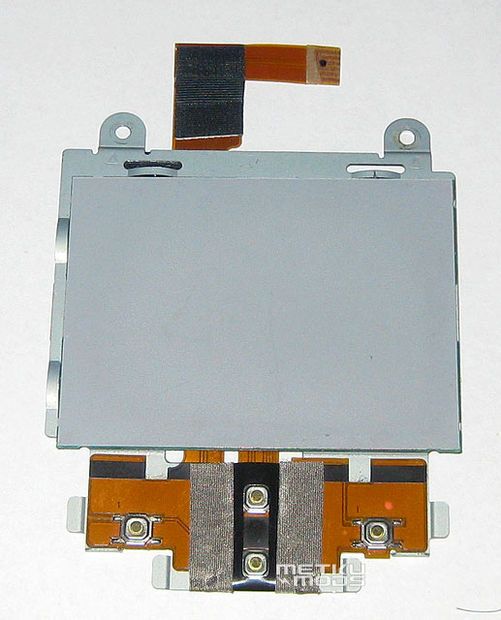
As it happens the PS/2 communication is not that difficult to achieve with an Arduino board. Kristopher has written an Arduino/Wiring library that offers all the functionality that we need at this point.
I will be using the MAX7219 Led Controller too and for this one can use LedControl library , written by Eberhard Fahle.
Step 1: Putting the touchpad together
I happened to find this TouchPad from inside a dead Fujitsu Siemens laptop. Model number for the pad is ALPS JCI-S1S. These kind of modules are easy to source also from ebay etc.
Ground and supply voltage pins are usually easy to guess just by looking at the circuit board but the data and clock pins were found by just pure trial and error method.
As the flexible cable is not the best suited for use with Arduino, I soldered better wires for the pins. Hot glue was used to make the connection more secure.
Step 2: Coding – Part I
Here are both the TouchPad and the 8×8 Ledmatrix hooked up to Arduino. Touchpad uses the 5 and 6 pins on Arduino and the MAX7219 utilizes the pins 10, 11 and 12. What goes were can be easy seen inside the code.
TouchPad reports the movement of the finger. One gets a pair of coordinates that indicated the amount of movement and the direction from the last position. For example -12, 2 would mean a swipe towards 10 o’clock and the X-axis movement being faster.
As it turns out, even the tap functionality works perfectly.
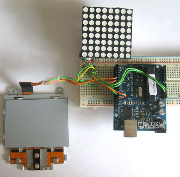
The code:
// Arduino + Laptop TouchPad. Basic functionality
//
// http://Metku.net
// Jani Pönkkö
// 23.07.2009
#include “PS2Mouse.h”
#include “LedControl.h”
#define MDATA 5 // touchpad ps/2 data pin
#define MCLK 6 // touchpad ps/2 clock pin
#define SENSITIVITY 5 // amount of movement needed to get a reaction
For more detail: Arduino + Laptop Touchpad
- How does the touchpad communicate with the Arduino?
The touchpad operates with the PS/2 standard and connects directly to a PS/2 connector on the Arduino. - Which library handles the touchpad functionality?
Kristopher wrote an Arduino/Wiring library that provides the necessary PS/2 communication functionality. - What components are required for the LED display?
A MAX7219 Led Controller and an 8x8 Ledmatrix are used with the LedControl library written by Eberhard Fahle. - Where can I source this specific touchpad model?
Modules like the ALPS JCI-S1S are easy to source from eBay or similar markets. - How were the data and clock pins identified?
The data and clock pins were found using a pure trial and error method after guessing the ground and supply voltage pins. - Why was hot glue used during assembly?
Hot glue was applied to make the soldered wire connections more secure since the flexible cable is not ideal for Arduino use. - What do the coordinate values from the touchpad represent?
The touchpad reports finger movement as a pair of coordinates indicating the amount of movement and direction from the last position. - Does the project support tapping functionality?
Yes, the code confirms that even the tap functionality works perfectly.
