
Summary of Retablillo de las Maravillas v1.0
Summary (under 100 words): The project implements interactive moving-platform gameplay with electromechanical characters as on-off switches, a translucent acrylic LED interface, and motor/I/O control. Characters use laser-cut MDF, copper-film electrodes, and neodymium magnets to register contact and stay in place. A stepper motor is driven by an Arduino Uno and an A4988 driver on a custom milled PCB, all powered by a 12V battery. The interface includes LEDs, an on-off switch, and a push button that trigger motor and timer/score routines.
Parts used in the Retablillo de las Maravillas:
- 3mm laser-cut MDF sheets (for characters and support platforms)
- Flexible self-adhesive copper film (electrodes)
- Neodymium magnets (small)
- Loctite glue (for fixing magnets/electrodes)
- Color printed collage (for character faces/decoration)
- White translucent acrylic (etched interface panel)
- Colored LEDs (inserted in the acrylic interface)
- On-off switch
- Push buttons (functional and decorative)
- 12V battery (power source)
- Arduino Uno (motor and system control)
- Pololu / Allegro A4988 Stepper Motor Driver Carrier (A4988 step-stick)
- 100 µF capacitor (on motor driver board)
- Connectors for 12V and 5V power
- Bipolar NEMA17 stepper motor (Wantai)
- Four bipolar motor cables
- Cables for electrode connections (soldered)
- Custom milled PCB (motor controller shield)
- iModela milling setup and end mill (used to mill PCB)
- Through-hole and SMD components for the PCB
4./ Interactivity & electronics
4.1/ Switches / characters
4.2/ Screen / interface
4.3/ Motor controller
4.4/ I/O controller & interface
[4./ electronics]
[4.1/ switches / characters]
The characters on top of the moving platform function, as interfaces, actually as on-off switches. While standing in its position on the platform that keep a switch on. Once they are knocked off the switch is off. The characters are built once again with 3mm laser cut MDF, and made of a circular platform, connectors and a silhoutte. On top of the silhouette and color printed collage is glued to make the figures attractive and, if so desired, recognizable.
This is achieved setting two electrodes on the surface of the moving platform that are connected by a continuous conductive surface when the figures are on top of them. The material solution of it was using flexible self-adhesive copper film for both ends of the switch, taking care to have it as perfectly flashed on the surface as possible. On the lower side of the platform a cable is soldered to each of the electrodes connecting to the I/O board.
A secondary problem was to keep the characters reasonably in place while the platform is moving left to right and back. This is achieved using small neodimio magnets that are embedded in the precisely cut MDF pieces. It was important to finely regulate the distance between magnets not to make the figures impossible to knock off with the light balls to be used in the game. Once determined the distance, the magnets were fixed in its place with some drops of Loctite glue.
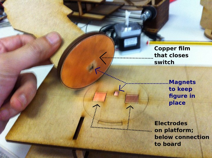
The figues still move a bit, and in a future version, two pairs of magnets could be used for each of the figures to achieve a more stable configuration.
The electrodes are made enveloping MDF pieces with the right dimensions in flexible copper film, so that the contact can be made on the top of the platform and cables can be soldered in the lower part. The neodimio magnets that we had in the lab from other projects need to be adjusted to find the right strength for the figures, so that they stay in place when the platform moves but that they can be knocked down with a softball. Some testing were made with the platform in movement to make sure the electrical connection was stable. Once the position of the electrodes and the magnets were fixed i used some Loctite glue to keep them in the exact place.
[4.2/ screen interface]
As advanced before, after considering various alternatives such using an LCD screen or a Python+Tkinter interface on a computer screen, a quite low tech and efficient design was finally chosen for the interface.
It consists on a white translucent acrylic, etched and equipped with various colored LEDs, as well as two functional switches [actually an on-off switch and a push button]. Two other push buttons are placed in the interface, but ended up having no function, and just looking cool 🙂 _ The LEDs inserted in the translucent acrylic glow in a attractive and quite visible fashion.
The system works as follows: The on-off switch connects and disconnects the system. The first time it is turned on two parallel routines [motor and timer+score] get triggered lasting for approximately 30 seconds. For the next iteration the player can press the push button that triggers the routines every time it is pressed. To turn the system off, the player presses the on-off switch.
The whole system is powered by a 12V battery, giving it an autonomy of several hours.
[4.3/ motor controller]
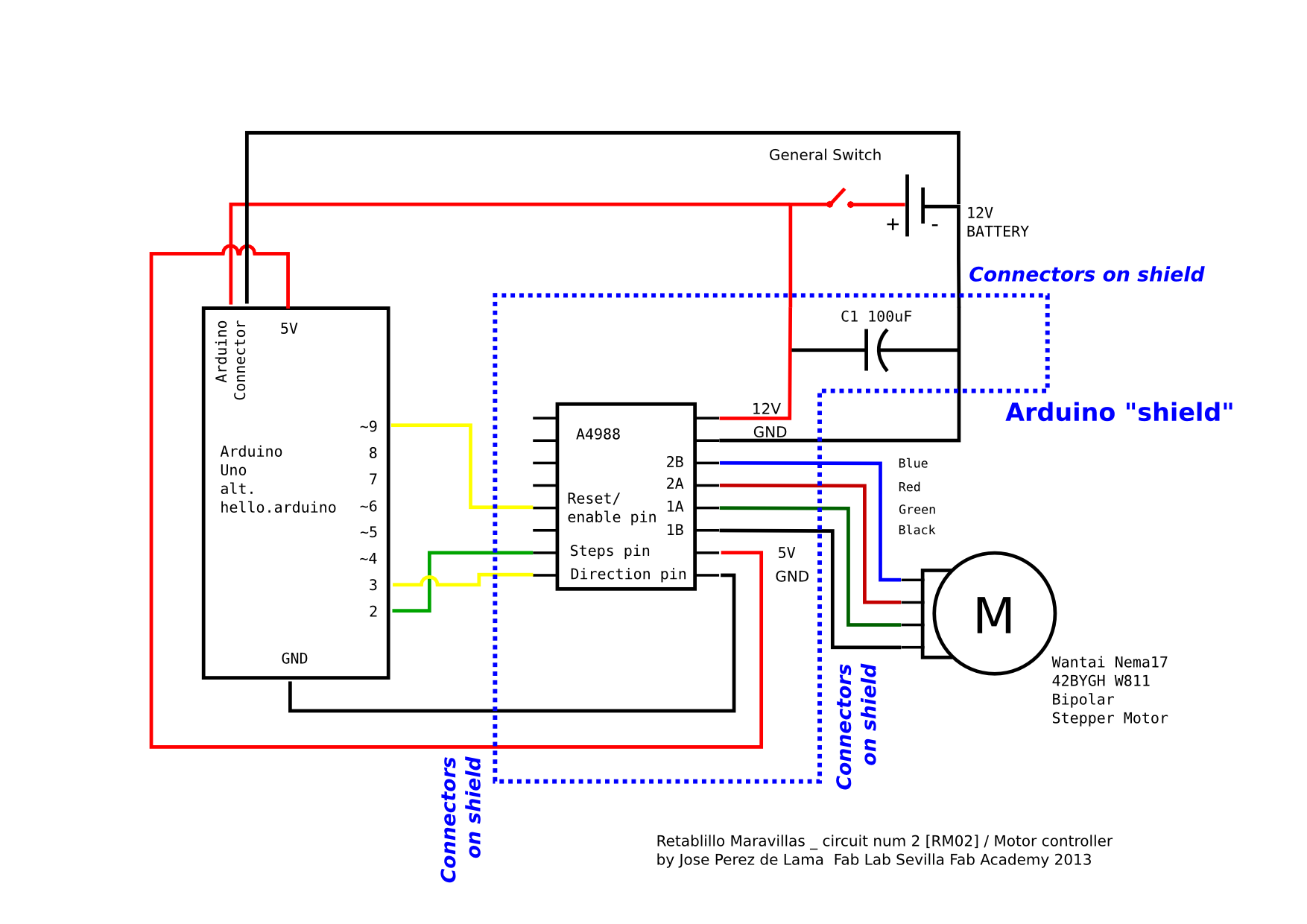
The stepper motor is controlled by an Arduino Uno and an ad hoc designed and fabricated simple board that houses a Pololu / Allegro A4988 mini board, – “A4988 Stepper Motor Driver Carrier” [http://www.pololu.com/catalog/product/1182] -, a 100uF capacitor and a set of connectors for 12V and 5V power + the four bipolar motor cables + the three connections to an Arduino Uno.
A schematic design was made with Inkscape, and then turned into the actual circuit design and milling files for the iModela with Rhinoceros; the file exported to the iModela, eventually was an “.ai”, an Adobe Illustrator file, that can be generated from Rhino [see images and links to files below].
The board was milled with the iModela, using a 4mm [1/64″] end mill – eventually! – that we were able to use thanks to a special adaptor/connector supplied by Roland Spain at the Fab Lab Iberia founding meeting in Barcelona. Compared to the 45º mills we had been using all through the academy the results using the 4mm end mill were extremely good. The board combines smd [capacitor] with through hole components [connectors].
The intelligence, as mentioned, is run by an Arduino Uno. We tried to make it with our own fabricated Arduino, but after trying four times in the lab with hello Arduino and Fab Kit 2.0 we didn’t manage to make it work yet.
A laser cut and etched 3mm MDF platform supports and gives stability to both boards. Both of boards are powered by the 12V battery – connecting to the Arduino through its own connector that i soldered too. The Arduino powered with 12V, regulates its own voltage, and provides the second board with 5V, through the 5V (and GND) pins. This allows for a single power source for all the system,- it is used to power a second Arduino in charge of the I/O system, too.
The system has been designed following the instructions in the Pololu web page and data sheet, as well as Igna94Igna’s, a local young colleague, online instructions [and code].
Above the connection diagram provided by Pololu for the Allegro A4988 motor controller “step-stick”.
And this one is my adaptation of the Pololu / Allegro diagram [http://www.pololu.com/catalog/product/1182] to be used in my configuration with Arduino and a Nema17 Wantai bipolar stepper motor supplied by reprapworld.com [http://reprap.org/wiki/NEMA_17_Stepper_motor] – that i had used before for the Reprap Prusa i2 that we made in former classes during the Academy. A larger version of the above image can be seen using “view image” in Mozilla / Chromium. The additional connections and the recommended 100uF capacitor, plus the A4988 are set in a “shield” as seen in the following drawings and images.
Rhinoceros image captures for the motor controller PCB design and milling file:
Download Rhinoceros file >> download link | alt download link [without .3dm extension]
Milling was a slow process. Eventually i was able to mill with a 1/64″ end mill – instead of the 45º that we had been using up to now – thanks to a special connector provided by Roland Iberia, and some mills sent to us by Nuria from Fab Lab Leon – thanks! -. The first board milled with the end mill came out perfect… But… I hadn’t realize that because i was using through hole technique for some of the components, i should had milled it upside down… Before, in the first board i had made minor mistakes, while in the third board some tracks didn’t come out well; so i ended up milling at least four boards until i got a truly great one… Here are some pics of the process:
For more detail: Retablillo de las Maravillas v1.0
- How do the characters function as switches?
They complete a circuit by bridging two electrodes on the moving platform with conductive copper film while standing on them; when knocked off the circuit opens and the switch is off. - What materials are used to make the characters?
Characters are made from 3mm laser-cut MDF, a circular platform, connectors, a silhouette, and a color printed collage glued on top. - How are the characters kept in place on the moving platform?
Small neodymium magnets embedded in the MDF hold characters in place; magnet distance was tuned so they can still be knocked off by a softball. - What is the interface design for the screen?
The interface is a white translucent etched acrylic panel with colored LEDs, an on-off switch, and push buttons, powered by a 12V battery. - How does the system start and run its routines?
Turning on the on-off switch triggers two parallel routines (motor and timer+score) for about 30 seconds; a push button can trigger routines for subsequent iterations. - Which motor controller and board are used?
An Arduino Uno controls the stepper via a custom board housing a Pololu Allegro A4988 stepper motor driver carrier and a 100 µF capacitor. - How is the whole system powered?
The system is powered by a single 12V battery that supplies the Arduino and through it the 5V for the rest of the system. - How was the motor controller PCB fabricated?
The PCB was designed (Inkscape/Rhinoceros), exported as an Adobe Illustrator file, and milled on an iModela using a 1/64" end mill. - Were there any fabrication challenges with the PCB?
Yes; multiple iterations were milled because of orientation mistakes and track issues, and milling was slow until a proper 1/64" end mill and adapter were used. - Can the characters be made more stable in future versions?
Yes; the article suggests using two pairs of magnets per figure to achieve a more stable configuration.