
Summary of Hack a TowerPro Micro Servo to Spin 360 / Continuous Rotation
This article provides a step-by-step guide on modifying a TowerPro micro servo to achieve continuous rotation (360 degrees) for use as a drive motor. The process involves disassembling the servo, replacing the internal 5k potentiometer with two 2.2k resistors, and removing the physical stop collar that limits rotation.
Parts used in the Hack a TowerPro Micro Servo:
- Rotary tool or utility knife
- Very small screwdriver (phillips)
- Soldering pencil and solder
- Wire snips
- Needle nose pliers
- Two 2.2k resistors
- Helping Hands (AKA 3rd hand)
Hey guys! Since I’ve got my servos, I’ve had two that I set aside for hacking. So, coming to my favorite website for help, I was sorely disappointed when I couldn’t seem to find any instructables on how to mod a micro servo. After viewing a few, I went to my workbench and got to work. I was very surprised when I opened up my micro servo and found it to be slightly different then the bigger servos. So, I decided I would make a guide on how to hack into your servo! So what are we waiting for? Lets get started.
But then you ask, doesn’t this defeat the whole purpose of a servo? Well, no. We just utilize the gearbox, so that we can use this motor as a drive motor for a robot. So now, let’s really get started!
Step 1: Ingredients:
Ingredients needed: (no, not food ingredients unfortunately)
- Rotary tool or a utility knife
- Very small screwdriver (phillips)
- Soldering pencil* and solder
- Wire snips
- Needle noes pliers
- 2x 2.2k resistors
- Helping Hands (AKA 3rd hand) BTW check out this awesome instructable on making helping hands. Thanks rstraugh!&
- 10 minutes

Step 2: Disassembly
First remove any servo arms, legs, and limbs from the servo.
Then, using a very small screwdriver, unscrew the four screws on the bottom of the servo. Be very careful not to lose these.
Watch the video for the disassembly of the gears. The top main gear my be hard in coming off. You can see I had a little trouble getting it off in the video.
Step 3: That 5k Potentiometer
Now we are going to turn our focus on the 5k pot. Here is were it’s different from the bigger servos. The shaft of the pot is also the shaft on which the gears sit on. So, we cannot get rid of the potentiometer, but we must keep it.
That being said, we must unsolder the 5k variable potentiometer, and solder on 2 [2.2K] resistors. Unsolder the wires on both ends, off of the PCB and potentiometer. Save these wires for a later project.
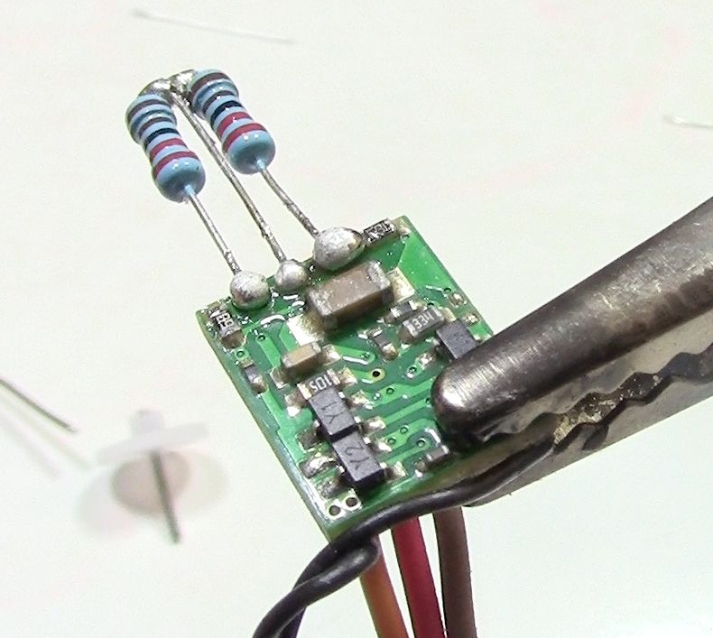
Take two 2.2K resistors and and bend the top leads over. Then, using the helping hands secure them like you see in the picture. Now solder these two top ends together. Get them as close to each other as you possible can. There should be two leads in the middle. Since this would make it harder to solder bend this wire up and cut it off. You should now have 3 leads.
Solder this new resistor to the PCB as shown in the last picture. Upon request, I made a horrible video of me soldering these on. It’s not the best, but at least it held. For instructions on soldering. . .
Noahw and his amazing instructable http://www.instructables.com/id/How-to-solder/
&
CuriousInventor.com http://www.instructables.com/id/How-to-Solder-Videos%3a-Why-is-soldering-difficult-s/
Now we must remove the collar that stops the potentiometer from spinning 360. Note, you may need to use needle nose pliers to peel off this plastic. In my case, I had already broken the collar when I was trying to get the gears out. See the video, and see what needs to happen. There also might be a metal stop like my other servo had. Your smart, just figure out how to allow the potentiometer to spin freely, but keeping it intact.
Finally, we need to put the potentiometer back into its original place. But first, we need to bend the leads over them selves inward, so that it won’t be in our way later on. Bend the leads over, the put back in it’s spot. Make sure it’s sitting properly on the plastic.
For more detail: Hack a TowerPro Micro Servo to Spin 360 / Continuous Rotation
- Why would someone modify a servo instead of buying a continuous rotation one?
The author found it difficult to find guides online and decided to create their own method using existing parts. - Does hacking the servo defeat its purpose?
No, because the gearbox is utilized to use the motor as a drive motor for a robot. - What tools are required to start the project?
You need a rotary tool or utility knife, a very small screwdriver, a soldering pencil, wire snips, needle nose pliers, and helping hands. - Can you remove the potentiometer completely during this modification?
No, the shaft of the pot is also the shaft on which the gears sit, so it must be kept. - What components replace the original 5k variable potentiometer?
Two 2.2k resistors are unsoldered from the PCB and soldered together to replace the potentiometer. - How do you allow the potentiometer to spin freely after modification?
You must remove the plastic collar or metal stop that prevents the potentiometer from spinning 360 degrees. - What should be done with the leads of the new resistor setup?
The top leads are bent over and soldered together, while the middle leads are cut off to leave three total leads. - Is it necessary to save the wires removed from the original potentiometer?
Yes, the article suggests saving these wires for a later project.
