They day I read at hackaday (http://hackaday.com/tag/esp8266/) that a new $5 wifi module was available, I order a few of them to test. Now, a few weeks later I want to share my experience.
This is a very simple demo using the ESP8266 and Arduino to update a remote server (https://thingspeak.com/) using a digital temperature sensor.
These are really exciting times for the Internet of Things (r)evolution. Prices are coming down and the Maker community is eager to develop the next generation of all things connected.
The following setup could be done under $20. This is using off the shelf “pricey” components (like Arduino), but you could program your own MCU with UART support and make it cheaper.
Step 1: Materials
- 1 x ESP8266 (http://www.electrodragon.com/product/esp8266-wi07c-wifi-module/)
- 1 x Arduino Pro Mini 328 – 3.3V/8MHz (https://www.sparkfun.com/products/11114)
- 1 x DS18B20 Digital Temperature Sensor (http://www.mouser.com/ProductDetail/Maxim-Integrat…
- 1 x 4.7k resistor
- 1 x Power supply (3.3V up to 12V, I used a 9v)
Step 2: ESP8266 Setup
This is where things got tricky. I spent a lot of time testing different configurations. Note that are two version of the ESP8266 going around. The first one has the notification LEDs right next to the board pins. The second one (newer) has the LEDs by the antenna. I have the second one.
The best results came when I loaded V0.922 which allowed me to change the baud rate to 9600. Follow these steps to load this firmware.
http://www.electrodragon.com/w/Wi07c#Firmware_uploading_tool
The best way to test a good connection is by using a USB-to-TTL cable and using a terminal like CoolTerm. Here is the command to change the baud rate:
- AT+CIOBAUD=9600
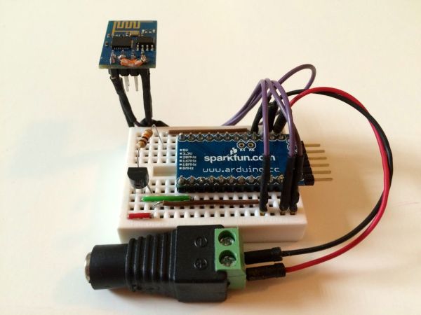
These are the pin connections I used on ESP8266 to USB-to-TTL. I used the regulated 3.3v vcc of the Arduino to power the ESP8266. I know that Arduino vcc 3.3v max is output is 150 mA and ESP8266 will peak at 240 mA. But at the time I had no other regulated 3.3v available. Regular usage for the ESP8266 is at 70mA.
Remember to connect GPIO0 to GND when you are uploading new firmware. After that remove for normal operation.
—-
GND –> GND (power source) | GPIO2 | GPIO0 | URXD –> TX (USB-to-TTL)
UTXD –> RX (USB-to-TTL) | CH_PD <–> VCC | RST | VCC –> VCC (power source)
———————————————————————————————————
*Note also had to do USB-to-TTL GND to Arduino GND
For more detail: ESP8266 Wifi Temperature Logger