
Summary of Interfacing a Digital Micrometer to a Microcontroller
Summary: This project connects a Mitutoyo digital micrometer to an Arduino to read the micrometer's 52-character reversed-bit data stream, reconstruct measurements, and display results on a VGA monitor via a 4D Systems uVGA-II. The Mitutoyo cable wiring, simple interface electronics (PN2222A, resistors, header, pushbutton), and Arduino code for clocked bit reading and byte assembly are described.
Parts used in the Mitutoyo digital micrometer to Arduino interface:
- Mitutoyo 293-335 Coolant Proof LCD Micrometer (0-1"/0-25.4mm, SPC Output)
- Mitutoyo 05CZA662 Digimatic Cable, 40", With Data Switch
- Arduino Mega or compatible
- µVGA-II (4D Systems uVGA-II PICASO QVGA/VGA/WVGA Graphics Controller)
- Protoshield (recommended)
- 2 PN2222A transistors
- Four 10k Ohm resistors
- 2x5 shrouded header
- One momentary pushbutton
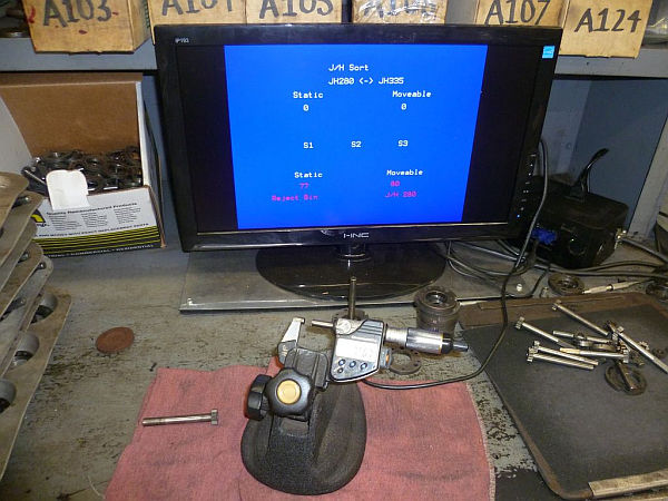
We had a project that required connection to a digital micrometer with a data output jack. The idea was to connect a microcontroller to the micrometer, to read the measurements and make decisions based on the readings. The micrometers that we used are made by Mitutoyo, and have a funky 52 character data stream in reverse bit order. The microcontroller we chose is the Arduino, and we used a 4D systems uVGA-II to take serial output from the Arduino and display it on a VGA monitor. Parts available from Hacktronics. Email me if you want a kit.
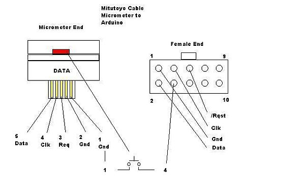
Step 1: Mitutoyo Cable Schematic
This is a diagram showing how the Mitutoyo cable is wired. There is a red “data” button on the micrometer end of the cable that we were not using in this application, so we decided to use it as a “menu” button.
Step 2: Connecting the cable to the Arduino
The Arduino connects to the Mitutoyo cable with a few components. A 2×5 shrouded header that mates to the female plug on the cable, a PN2222A transistor, and two 10k Ohm resistors. One resistor is used with the PN2222A to protect the micrometer (or caliper) from excessive voltage, the other to bias the “menu” button to +5vdc.
Step 3: Reading the Mitutoyo output
digitalWrite(req, HIGH); // generate set request
for( i = 0; i < 13; i++ ) {
k = 0;
for (j = 0; j < 4; j++) {
while( digitalRead(clk) == LOW) { } // hold until clock is high
while( digitalRead(clk) == HIGH) { } // hold until clock is low
bitWrite(k, j, (digitalRead(dat) & 0x1)); // read data bits, and reverse order )
}
// extract data
mydata[i] = k;
// sign = mydata[4];
// decimal = mydata[11];
// units = mydata[12];
}
// assemble measurement from bytes
char buf[7];
for(int lp=0;lp<6;lp++)
buf[lp]=mydata[lp+5]+’0′;
buf[6]=0;
num=atol(buf); //assembled measurement, no decimal place added
// Serial.println(num);
 Digimatic interface.pdf164 KB
Mitutoyo 05CZA662, Digimatic Cable, 40″, With Data Switch for Coolant Proof Micrometers
µVGA-II(SGC) PICASO QVGA/VGA/WVGA Graphics Controller
2 PN2222A transistors
four 10k Ohm resistors
2×5 shrouded header
one momentary pushbutton
For more detail: Interfacing a Digital Micrometer to a Microcontroller
- How is the Mitutoyo cable wired to the interface?
The article provides a cable schematic showing wiring and mentions using the micrometer's red data button as a menu button. - How is the Mitutoyo cable connected to the Arduino?
Use a 2x5 shrouded header that mates to the cable, a PN2222A transistor, and two 10k resistors: one to protect the micrometer from excess voltage and one to bias the menu button to +5 VDC. - What components are used to protect the micrometer signal?
A PN2222A transistor and a 10k Ohm resistor are used to protect the micrometer from excessive voltage. - How is the micrometer data read by the Arduino?
The Arduino toggles a request line, then clocks in bits by waiting for clock highs and lows, reads data bits, reverses their order per nibble, stores bytes, and assembles the measurement string in code. - What is done with the assembled measurement?
The code assembles numeric characters into a buffer, converts it to a long integer (atol) as the assembled measurement without the decimal place, and can print it via Serial. - How many data bytes are read from the micrometer?
The code reads 13 bytes into an array mydata[] and uses bytes 5–10 to build the measurement digits. - How is the display handled in the project?
Serial output from the Arduino is sent to a 4D Systems uVGA-II graphics controller to display the measurement on a VGA monitor. - Can the micrometer's data switch be repurposed?
Yes, the article states the red data button on the micrometer cable was repurposed as a menu button in this application.