
Summary of Radioactive isotope decay simulation
This article describes a LabVIEW educational exercise where students simulate radioactive decay analysis using Arduino boards as programmable sources. This approach solves hardware scarcity and reset difficulties, allowing repeated testing without waiting for actual isotope decay. The system uses an LED on the Arduino to provide visual feedback during debugging.
Parts used in Radioactive Isotope Decay Simulation:
- Arduino boards (specifically twelve units)
- LabVIEW software
- Pin 13 output
- LED indicator
- Python plotting tool
My students need to learn LabVIEW —I know, it’s proprietary software, and expensive, but until a viable open-source equivalent comes along we’re stuck with it— and one of the exercises I have them do is to make a program to analyze radioactive decay. This gives them experience in using counters, plotting data in real time, curve fitting, etc.
The problem arises when I have a dozen students and not so many good sources and detectors. During the students’ development of their LabVIEW program, they need multiple re-starts on the measurement. The program NEVER works right the first time, and if you’re using neutron-activated indium as a source it’s hard to “reset” it when you realize that your block diagram isn’t wired right.
I have a dozen Arduinos, though, and I’ve programmed them to behave as if they were radioactive sources. This way the students can try their program, fix their program, push the reset button on the Arduino and try the program again.
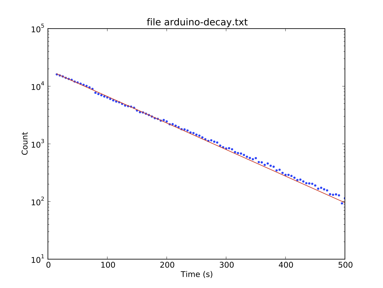
Here’s the code. I use pin 13 as an output since the LED allows students to see that it’s working, even when their program isn’t. The plot shown at the top of this page is actual data from the Arduino, as collected via a student LabVIEW program and plotted in Python. There’s a step in the data at about 80 seconds —not sure if that’s the Arduino or LabVIEW— but it works well enough for the job.
For more detail: Radioactive isotope decay simulation
-
Why use Arduinos instead of real radioactive sources?
Arduinos allow multiple restarts and fixes when programs fail, which is difficult with neutron-activated indium that cannot be easily reset. -
What pin is used for the output signal?
Pin 13 is used as an output to drive the LED. -
How do students verify the Arduino is working?
Students can see the LED light up, confirming the board is functioning even if their LabVIEW program has errors. -
Can this simulation be used with Python?
Yes, data collected from the Arduino via a student LabVIEW program was successfully plotted using Python. -
What skills do students gain from this exercise?
Students gain experience in using counters, plotting data in real time, and performing curve fitting. -
Is there an issue with the data plot shown?
The author notes a step in the data at about 80 seconds but states it works well enough for the job. -
Why is LabVIEW necessary for this specific curriculum?
There is currently no viable open-source equivalent to LabVIEW, so the proprietary software must be used.
