
Summary of Charlieplexed Arduino 8×8 LED Grid Display Shield made and simulated in 123D Circuits
This article details the design of an 8x8 Charlieplexed LED grid display shield using an Arduino. The project utilizes Charlieplexing to drive 72 LEDs with only 9 IO pins, eliminating the need for extra components. The author simulated the circuit in 123D Circuits before creating a PCB, writing custom software to animate frames using binary code.
Parts used in the Charlieplexed Arduino 8x8 LED Grid Display Shield:
- Arduino board
- LEDs (Red or Green)
- Current limiting resistors (10 Ohm to 100 Ohm)
- 123D Circuits simulation platform
- PCB for production
- Breadboardless circuit connections
edit: Wow, this won an awesome prize! Very many thanks guys!
Charlieplexing (http://wealoneonearth.blogspot.nl/2013/03/design-note-charlieplexing-led-matrices.html) is a powerful method for driving a large number of LEDs from a relatively small amount of IO pin and without using any extra components. The technique makes use of the fact that a LED will only let current through in one direction. So if you connect two LEDs to two IO pins, both reversed in direction, you can make the first LED light up by making one pin low and the other high. To make to other LED light, make the pin low which was high first and vice versa. Adding more LEDs to the system, you will be able to drive x2-x LEDs, where x is the number of IO pins you are using. So using 3 pins, you can use (32-3=9-3=) 6 LEDs, and using 9 pins, this increases to (92-9=81-9=) 72 LEDs.
Wanting to figure out how this method worked, but not having the parts around, I used the 123D Circuit website to make a simulation. Added bonus is that I could easily turn the simulation into a PCB for the production of an Arduino shield. The shield can be used as a simple display with 8×8 pixels. I wrote the software so that you can animate the frames yourself in binary code. Check it out in the following video. The blinking of the LEDs unfortunately is very faint in the software, but you’ll see it if you look closely.

See the schematics and simulation here: http://123d.circuits.io/circuits/102918-charlieplexed-arduino-8×8-led-grid-display-shield
Step 1: Make the (breadboardless) circuit
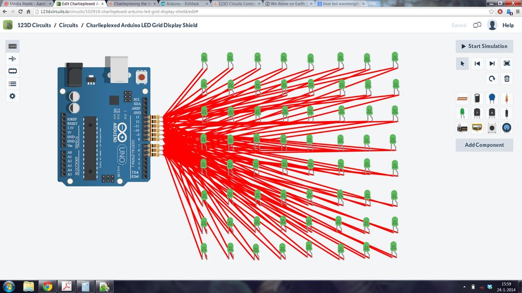
As described in the charlieplexing article a specific wiring is needed to get the right effect. First Arduino pin goes to all the – pins of the LEDS on the first row, the + pins of these LEDs go to Arduino pin 2, 3, 4 etc. The second Arduino pin goes to all the – pins of the LEDS on the second row, the + pins of these LEDs go to Arduino pin 1, 3, 4 etc. And so on for all the other pins.
First add the nine current limiting resistors at the pins of the Arduino. In the software I gave them a value of 100 Ohm, but in reality, 10 Ohm or even no resistor is preferred. This is because each LED will flash only very shortly, so it isn’t at much risk for burning up.
The work in 123D is very tedious, so after the resistors start with duplicating a whole lot of LEDs in a grid. I started with red LEDs, but later on I found that the blinking of green was more visible in the software, so I changed them all.
With the leds in place, start wiring. This needs to be done very neatly, or else you will lose track of everything. I started with all the direct connections of each resistor horizontally, followed by the connections vertically.
With this done, we can work on the code!
Step 2: Code
The code has four main parts:
- The animation frames
- The charlieplexing mapping
- The loop
- The led handler
1 The animation frames
To make it easy to program what is shown on our little display, I’ve made the code so you can just type in whatever you want displayed like what is shown in the next lines. 1 means that the light is on and 0 off. The B character is meant to Arduino knows it is binary code instead of one thousand hunder etc. etc.
{
    B10101010,
    B10101010,
    B10101010,
    B10101010,
    B10101010,
    B10101010,
    B10101010,
    B10101010
  },
    {
    B11111111,
    B00000000,
    B11111111,
    B00000000,
    B11111111,
    B00000000,
    B11111111,
    B00000000
}
2 The charlieplexing mapping
This is an array indicating which pins need to be connected to each other. The beauty of this table is that you can still make this same device work, even if you have made mistakes in wiring or have some other IO pins in use. If so, just change the values in the array!
3 The loop
The loop does nothing more than changing the frame number after a set amount of time. It calls the led handler as often as possible as to avoid flicker. You could easily combine the program with something else by just adding it here.
4 The led handler
This is where the magic happens. Basically, it steps through every LED, and checks if the current animation frame wants it on or off. Something which was hard to grasp for me earlier, was the bitlogic used to do this check. If you don’t get the explanation at the comments, try this tutorial: http://arduino.cc/en/Tutorial/BitMask
For more detail: Charlieplexed Arduino 8×8 LED Grid Display Shield made and simulated in 123D Circuits
-
How does Charlieplexing work?
It uses the fact that an LED only conducts current in one direction, allowing x^2-x LEDs to be driven by x IO pins. -
Can I use 9 pins to drive 72 LEDs?
Yes, using 9 pins allows you to drive 72 LEDs calculated as 9 squared minus 9. -
What resistor value is preferred for this project?
While the code uses 100 Ohm, 10 Ohm or no resistor is preferred because LEDs flash very briefly. -
Which color LEDs are more visible in the simulation?
Green LEDs were found to be more visible in the software than red LEDs. -
How do I program the animation frames?
You type in binary code where 1 means light on and 0 means light off, prefixed with B for Arduino. -
Can I change the wiring mapping in the code?
Yes, you can modify the charlieplexing mapping array to accommodate wiring mistakes or other IO pin usage. -
How does the loop function prevent flicker?
The loop calls the led handler as often as possible after changing the frame number at set intervals.
