
Summary of LED Matrix Bike Safety Backpack using arduino
This tutorial shows how to build a large, bright custom LED matrix backpack for bike visibility using individually-addressable RGB LEDs and an Arduino Pro Mini (or other Arduino). It covers spacing LEDs with 3-conductor conductive ribbon to make a bigger matrix, tinning pads with flux, soldering the first LED to the Arduino (data to DIN, 5V to 5+, GND to GND), then soldering remaining LEDs to the ribbon in rows, and attaching the finished matrix to a backpack or garment.
Parts used in the LED Matrix Backpack:
- Individually-addressable RGB LEDs
- Arduino Pro Mini (or any Arduino)
- FTDI cable (if using Pro Mini)
- 3-conductor conductive ribbon (or wire/conductive thread)
- Thin wire
- Basic soldering equipment (soldering iron, solder)
- Flux pen (optional)
- Needle and thread
- Cloth to cover LEDs (optional)
- Backpack (or jacket or other attachment)
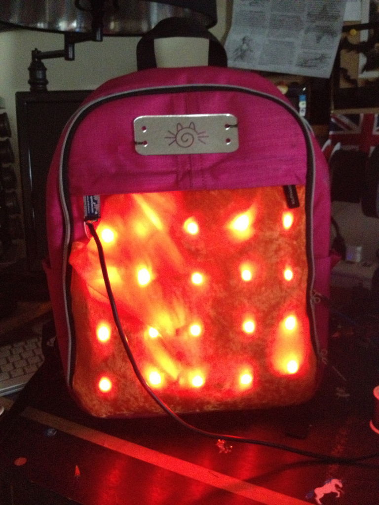
Biking around cars can be a frightening thing, and staying visible at night is crucial for your safety. This tutorial will teach you how to make a custom LED Matrix Backpack that is much larger and brighter than traditional rear bike lights.
Parts You’ll Need:
- Individually-addressable RGB LEDs
- Arduino Pro Mini (or any Arduino, this one is just conveniently small.)
- Note that if you use the Pro Mini, you will need an FTDI cable to program it.
- 3-Conductor Conductive Ribbon (wire or conductive thread will work too but this stuff is nice)
- Thin Wire
- Basic soldering equipment (soldering iron, solder, etc.)
- Flux Pen (optional)
- Needle and thread
- Some nice cloth to go over the LEDs (optional)
- A backpack (or jacket! or whatever you want to attach this to.)
To see videos of the finished project, click here!
Michelle Leonhart
@at0mbxmb | www.tinwhiskers.net

Wearable LED Matrix by Michelle Leonhart is licensed under a Creative Commons Attribution-ShareAlike 4.0 International License.
Step 1: Learn the Basics of Programming an LED Matrix
First things first, if you’ve never programmed an LED Matrix before, please check out my tutorial on How to Make an Individually Addressable LED Matrix. This will give you the foundation necessary to start this project.
Step 2: Separate Your LEDs with the 3-Conductor Conductive Ribbon
If you are made of money, you can skip this step and just use a ton of LEDs. But if you’re like me and would rather save the cash, you can make a much bigger LED matrix with fewer LEDs by spacing them out.
Decide how large you’d like your matrix to be, and how many LEDs you’d like per row/column. Depending on the size you want, snip your 3-Conductor Conductive Ribbon into pieces to separate out the LEDs.
Once your ribbon is cut into the correct sized pieces, it’s time to tin the tips. I highly recommend a Flux Pen. Flux helps solder flow easily onto your parts, and reduces the amount of time you have to leave the iron in contact with your project. This is especially crucial here, because the heat of your iron will melt the nylon in your ribbon if you hold it there too long.
When you’re done, there should be 3 tinned spots on both ends of the ribbon. Remember that both ends will be connected to LEDs.
Step 3: Solder the First LED to your Arduino
Your Arduino should have three wires coming from it:
- red (power)
- black (ground)
- blue (data)
Think about how you want your Arduino to fit into your project in terms of aesthetics and function. (I chose mind to be in the top left corner for easy programming.) Tin the pads of one side of your LED, and solder the wires from your Arduino to your LED like so:
- Blue wire solders to the “DIN” pad on the left side. This stands for “Data In”
- Red wire solders to the “5+” pad on the left side.
- Black wire solders to the “GND” pad on the left side.
Your LEDs may have a slightly different layout than mine. Compare yours to these from EpicTinker to see if they are the same. If not, you will have to mod your process accordingly.

Step 4: Solder the Rest of the LEDs to Your Ribbon
Just as you did with the ribbon, now tin the BOTTOM PADS on your LEDs. There are 6 pads total (3 per side), and each pad should have a little blob of solder on it when you’re done. Again, using a flux pen will make this faster and easier.
When your LEDs are tinned, they are ready to solder to your ribbon. Place your LED on TOP of your ribbon, with the tinned pads laying gently on top of the tinned tips of the ribbon. Use a tool to hold your ribbon down (NOT your hands! The ribbons will get hot!), and firmly press the tip of your iron into the TOP of the first pad on your LED until you see the solder flow between the pad and the ribbon. (Holding the tip of the iron at a slight angle while you do this is ideal.) Retract the iron, and continue to hold the ribbon down with a tool until the solder cools. Once it’s cool, give your ribbon and your LED a tug to ensure the connection is strong.
Repeat this for all pads, being mindful not to let the solder connect the pads together. Connected pads will cause a short circuit, and possibly break your project.
Make as many indivdual rows of LEDs as will fit in your chosen configuration, with as many LEDs per row as you’d like.
For more detail: LED Matrix Bike Safety Backpack using arduino
- What is the purpose of this LED Matrix Backpack?
To create a larger, brighter rear bike light matrix for improved visibility and safety at night. - What type of LEDs are used?
Individually-addressable RGB LEDs are used. - Which Arduino is recommended?
An Arduino Pro Mini is suggested, but any Arduino can be used. - Do I need an FTDI cable?
Yes, if you use the Pro Mini you will need an FTDI cable to program it. - Why use 3-conductor conductive ribbon?
It lets you space out LEDs to make a larger matrix with fewer LEDs; wire or conductive thread can also be used. - How do you connect the first LED to the Arduino?
Solder blue to DIN (data in), red to 5+ (power), and black to GND on the LED. - What soldering tips are recommended?
Tin pads before soldering, use a flux pen to help solder flow, and avoid holding the iron too long to prevent melting the ribbon. - How are LEDs attached to the ribbon?
Tin the bottom pads on LEDs, place LEDs on top of ribbon, then solder each pad to the ribbon without bridging pads.