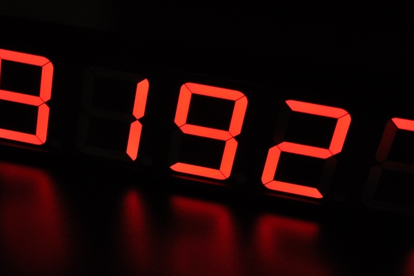
This project originated from a request of a friend. He asked me to build a so-called smile counter for their college dorm – a segmented display which can show a number. This number must increment every time someone pushed a button and should be memorized even if power goes out. The counter was counting smiles: every time a tenant would pass it by and was in a good mood, happy, smiling or anything in between, they would hit the button.
In order to have a processing unit as simple as it can get (and to consume a few of the salvaged ICs I had, and still have on stock), I decided to build this using counters, decoders and buffers – at least on digit level. The main controller is an Arduino Nano I also had on stock.
The enclosure was made from a wood “L” profile and ABS corners designed and printed for this very project, it turned out quite nice – I might end up using more of this enclosure concept in the future. The back was a piece of ESD material i salvaged from an ESD box.
Step 1: Thinking About What Needs to Be Accomplished
So I sat down and thought about what I needed to build this:
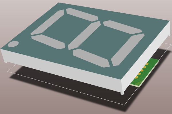
- A large display, visible from a couple of meters away (SA40-18SRWA)
- A low-side driver to switch the segments of the display (ULN2003A)
- A decade counter chip with 7 segment decoded outputs (CD4026BE)
- Five printed circuit boards for the five displays
- Discrete components like resistors, capacitors, transistors
- Main controller unit in the shape of an Arduino
- Hand tools, soldering equipment, benchtop instruments
Most of these were taken from my personal component stock, but I added links should anyone need them. Since I am based in Europe, I order most of the stuff from this polish website: www.tme.com
Even though I used to work with a certain PCB manufacturer until now, for this and for my upcoming projects I will stick with this new manufacturer I found thanks to instructables: NextPCB. I will say more about the boards at the corresponding step.
As for equipment, there has been quite an upgrade from the last time I shared an instructable, I moved and now have a much bigger “office”, considerably more equipment and – most important – a lot more desk space for the equipment, books, tools, PCs and other stuff I use for creating stuff. I might share a couple images of this new place I put together in an upcoming instructable.
All those listed above wouldn’t mean anything, were it not for the most important component: time. When thinking of the limited time I had, I must say that this project came around quite quickly. It took me around 50 hours to build this thing, write the code plus a bit more to to take pictures and to write the descriptions.
Step 2: Simulating the Circuit
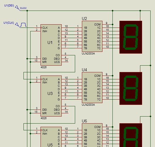
Simulations are generally a good idea to implement when constructing circuits, they help spot bad biasing, incorrect voltage dividers, currents larger than some components can handle, and so on. Even though my circuit is quite simple, I wanted to know for sure that the IC inputs are polarized as intended and I don’t end up having to negate the reset, or worse: cut traces on the nice factory PCBs.
The circuit shown on the above image can be continued to infinity, this version would use a single clock input instead of the independent clocking I ended up with. I made one stage and just had to copy a few more, just for the fun of it. The simulation works and I am happy to share it with anyone. The editor didn’t allow Proteus simulation files to be added, but I can e-mail it to anyone interested.
Step 3: Schematic Capture
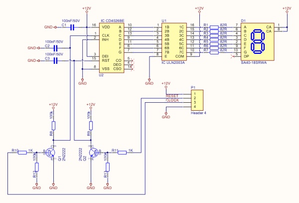
After one glance at the schematic one can see that it’s not very complicated. The schematic I attached to this step is for one digit only, imagine it multiplied by the number of digits you need. I needed five, which was convenient from the PCB ordering point of view – five pieces is always a minimum anyway, so nothing goes to waste!
The main components of this circuit are the counter IC, the driver, and the display. The rest of the components are just setting current limits, biasing to certain rails, decoupling noise, or level-shifting the Arduino’s 5V signals.
The counter IC – CD4026BE
This component turns the clock signal into counts on the display. This IC has the following inputs and outputs (apart from the power pins, which simply go on the 12V rail with decoupling caps) that we need to use:
- DEI – display enable – this can be toggled to enable/disable the display module. It would have been a nice alternative to showing leading zeros on the display, but nothing to worry about if you just bias it to 12V. Maybe it will motivate the tenants to smile more and make the zeros go away.
- CLK – clock input – the counter will increment by one at every rising edge seen on this pin. This pin is brought out on a pin header so the Arduino can connect to it easier. There is a transistor level shifter between the piin and the header!
- RST – reset input: the counter will reset to zero if there is a rising edge on this pin. This pin is also brough out on a pin header to allow the Arduino to reset the counter. There is a transistor level shifter between the piin and the header!
- INH – clock inhibit: this must be pulled low to enable increments on CLK rising edges. I had no special use, so this is just pulled low and allow every pulse on CLK to increment the counter.
The buffer IC – ULN2003A
This component is just an array of Darlington transistors packed into a neat DIP package. It has seven channels, exactly the amount we need for a seven segment display.
The display – SA40-18SRWA
The display has LEDs inside its segments. The number of series LEDs changes depending on the size of the segment. I decided not to allow half smiles so I killed off the DP segment. All other segments have two strings of 4 LEDs each, in parallel. The anodes of all segments are tied together to pins 1 and 8, the cathodes are connected to the rest according to the datasheet drawing. The datasheet specifies a 10V forward voltages on all segments other than the DP, and recommends a current of 20mA as a safe value. Since we have a 12V PSU, we will do the math like this:
RLED = (12V – 10V) / 0.02A = 100R
This is the resistor we will put in series with the segments to set the recommended 20mA running through the LEDs. The current flows from the 12V rail – display anode pins (1 and 8) – internal LED string – cathode pin – 100R resistor – ULN2003A internal transistor CE junction – ground. Whether or not the segment lights up depends only on the state of the ULN2003A transistor. If the transistor is turned on, current can flow through it and the LED segment lights up, if not, the segment turns off.
The counter IC offers decoded outputs, which means that we can route the output directly into the ULN2003A inputs.
Everything else
Other components include decoupling capacitors on the power pins of the counter, filtering capacitors on the clock and reset inputs of the counter, resistors, and a transistor based level shifter to allow for lower voltage triggering. Any small signal NPN transistor can be used, I don’t even know the exact type I used, but it is very likely that a 2N3904 will do just fine. I have a lot of desoldered components in stock, but ordered these by the hundreds off eBay as well. They are bundled together under a small signal NPN label.
Step 4: PCB Layout
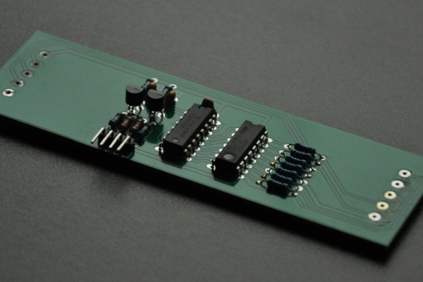
The layout couldn’t be simpler, as we are pretty lucky with the pin-outs of the two integrated circuits. I placed them at a fair amount of distance from each other so there still room for routing, the positioned the resistors in place, close to the ULN2003A, and distributed them evenly so their 3D models don’t collide. This allows for easier soldering later on. Just as a general good practice: I placed the decoupling capacitor as close as possible to the IC, then just packed the level shifters and filter capacitors into identical groups, and rotated/moved them around until I got a satisfying layout.
As I said in the introductory step, I recently switched the PCB manufacturer I work with. Thanks to the instructables website I got in contact with a sales representative from NextPCB who told me about their capabilities and their reward system. If anyone ordered a PCB with my referral link, I’d get reward points which I can convert into PCBs later! The boards were impeccable, and if luck strikes with many people using my link to order, I will be able to keep the PCBs and instructables coming with less cost. If you wish to order from them, feel free to use my link!
Step 5: They Arrived! Assembly of the PCB and Enclosure
Circuit boards
The assembly rule of thumb is to begin with the shortest components, although this is mostly valid in cases when the component size differs with a lot. In this kind of through hole design (which is very old school, but I like it for some reason) one probably will get away with almost any soldering sequence. Just make sure you solder the display the last, as the other components are between the display and the board!
I assembled all five boards but soldered 4080s instead of 4026s.. needless to say I soldered EVERYTHING, including the displays, so at the end of the day I was poorer with a full roll of solder wick, and 2 hours worth of rework. I eventually got everything down and replaced without damaging PCBs or components. I didn’t solder the displays back, though, so I can see it work before everything was turned in concrete again..
Testing this was pretty simple, one does not need an Arduino to do it. I just powered the modules on through the power pins of the pin header, then used tweezers to short the transistor base pins to the 12V pin to clock it. I tested all five segments like this, and they all worked at first try. After the successful tests I soldered the displays onto the boards, and the five modules were ready.
Enclosure
I bought this L shaped wooden stick a while ago for another project, but I ended up not using it. Since I was using up old components anyway, I ended up using it as the walls of my enclosure. Unfortunately, I am not very good with wood cutting and 45 degree angles, so I wasn’t much surprised when the edges didn’t align too well. I was afraid that glue won’t hold strong enough if there isn’t enough surface touching, so I decided to 3D print some corners and stiffening pieces to gain more rigidity.
After the box was assembled, I designed a 45 angle cutting jig for future projects using this kind of L profile as enclosure walls. The design still needs a bit of adjusting, but if the next box turns out nice, I will share the design and the steps needed to create it in another instructable.
Anyway, the print didn’t take long and after a half hour I had some nice components to save me from a terrible-looking enclosure. I aligned the L profiles (with the displays inside so they surely fit later) and marked the holes I needed to drill. I drilled 2.4mm holes and used 3mm screws to fix everything together. The enclosure could look better, so I sprayed a few layers of black paint until it looked quite OK. I didn’t know this but it looks like wood is absorbing the type of spray paint I used, it took at least 5 layers to make it look like you can see it on the pictures.
Step 6: Designing and Printing Some Enclosure Holder Components
The only 3D design tool I can use is TinkerCAD. I had some moments with Inventor and Aspire, but I completely forgot how to use those. I came back to the good old shape-based TinkerCAD, made some measurements on the wooden profile, and started drawing. I even added small holes so I can center-punch the holes better on the profiles. Printing was done on my FlashForge Dreamer 3D printer, I attached a photo of it to this step.
An inline thank you note for this website…
As a hobbyist, I must say that my office/workshop was missing a 3D printer for too long, it was an unreachable dream-tool for quite some time. With my GoldFish project I submitted to instructables around 2 years ago my dream finally came true – I used my grand prize to buy a printer so I can keep the projects, intructables and other hacks coming. It has been a great and essential addition to my tool belt. Thanks again, instructables!!
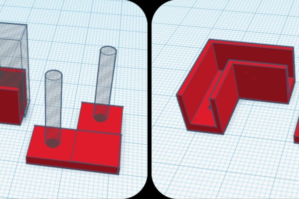
Back to the counter project: I attached a TinkerCad screenshot that reveals how the designs van be broken down into simple bricks and cylinders. I used the dimensions of my wooden L profile. Even so, the corners didn’t align very well after assembly. This was due to my cut not being at a perfect 45 degree angle, and the corners not aligning perfectly with the edges. I poured some glue into the corners, waited until it dried, then used sand paper to smooth it up – see the picture of a corrected edge before painting.
After the sanding process I spray-painted the enclosure with multiple layers of black paint. It looks like this isn’t the best choice of paint, though, since it took me around five layers to get the wood at a decent darkness level.
Step 7: Adding the Controller and Wiring Everything Together
Even though I put pin headers for power and signals, I decided to solder everything on the bottom side of the PCB with wires. I just didn’t want to go complicated and crimp any cables for this, this was the easiest solution that surely wont move around the enclosure, even if the counter falls down, is hit or something similar.
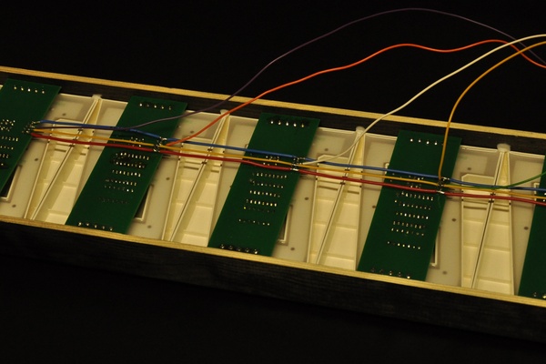
Three of the 4 signals are common for each segment: +12V, GND and RESET. I cut three wires based on in-box measurements, used a cutter to peel off the isolation, then soldered them onto the pins, bridging them together. Since the digits weren’t imagined to step one another, I soldered the CLOCK pins together with the pins D2, D3, D4, D5 and D6 of the Arduino Nano. The RESET signal was soldered to pin D7.
The signal that steps the counter is coming from a button, and is fed into pin D8 of the Nano. I built a pull-down resistor configuration: whenever the button is pressed, there is 5V on the pin, whenever it’s released, there is 0V on the pin. There is a 10nF capacitor on the button terminals to eat the bounce coming from the mechanical imperfection of the button.
At the time I was using the USB as power source for the Arduino and my benchtop PSU as the power source of the digits (+12V) so the ground rails of the two had to be soldered together in order to have a common reference point. You can see a blue wire connected to the Arduino GND pin, that’s it. In the end product there will only be a single PSU – a 12V power brick. To power the 5V Arduino I simply routed the 12V onto the VIN pin of the Arduino Nano.
Source: 88888: the Electronic Smile Counter