Summary of 3D4x Game: 3D 4x4x4 Tic-Tac-Toe
This article details the construction of a 3D Tic-Tac-Toe game featuring a 4x4x4 cube where players aim to align four LEDs in any direction to win. The project utilizes an Arduino Uno and PL9823 addressable LEDs mounted on styrofoam panels reinforced with wooden skewers. It includes a comprehensive list of components and tools required for assembly, along with step-by-step instructions for building the grid structure and soldering connections using repurposed ethernet cables.
Parts used in the 3D4x Game: 3D 4x4x4 Tic-Tac-Toe:
- Arduino Uno
- PL9823 LEDs (at least 64)
- Wooden skewer sticks (24cm long)
- Wiring from old ethernet cable
- Momentary state buttons
- 7 Resistors (220Ohm)
- Breadboards (2 total)
- Foam polystyrene board (~2x30x30cm)
- Foam polystyrene block (~7x25x25cm)
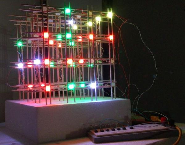
Are you tired of playing the same, old, boring, 2-dimensional tic-tac-toe?? Well, we have the solution for you! Tic-tac-toe in 3-dimensions!!! For 2 players, in this 4x4x4 cube, get 4 LEDs in a row (in any direction) and you win! You make it. You play it. In this Article we will Briefly describe 3D4x Game: 3D 4x4x4 Tic-Tac-Toe
3D4x Game: 3D 4x4x4 Tic-Tac-Toe
Step 1: Gather Components and Tools
The most essential component of this 3D Tic-Tac-Toe is the LED. We chose the PL9823 which already has an integrated controller inside. It has four pins (Data-in, Voltage-Supply, Ground, Data-Out), and allows you to easily address and control the color of the LED. The grid structure can be built in many different ways, but for us this was the cheapest, sturdiest, and most aesthetic option.
Component List:
- Arduino (we used Uno)
- PL9823 LEDs (at least 64)
- Wooden skewer sticks (24cm long)
- Wiring (we used the insides of an old ethernet cable)
- Buttons (momentary state)
- 7 Resistors (220Ohm)
- Breadboards (1 for buttons and playing, 1 for easy panel connections to Arduino)
- Foam polystyrene board (~2x30x30cm to make the panels)
- Foam polystyrene block (~7x25x25cm as the base for the entire grid)
Tool List:
- Soldering iron
- Soldering tin
- Glue
- Straightedge with ruler
- Pliers
- Wire strippers
- Wire cutters
- Scissors
- Marker
- Pen
- Tweezers
Step 2: Make the Grid
We make 4 panels of 4×4 LEDs individually.
- 00: Get styrofoam to make the panel layout. Draw the pattern. In this case, we used 6cm spacing between LEDs with 2cm on the ends.
- 01: Insert the LED pins into the styrofoam. Important! Make sure you insert all the LEDs with the same orientation. In our case, we chose the output pin to be towards the left.
- 02: Now place the wooden rod skewer sticks on both sides of the LEDs in rows, making sure the points all face the same direction. Glue the stick to the sides of the LED bulbs and let dry.
- 03: Do the same for the columns of wooden rod skewer sticks on both sides of the LEDs, making sure the points all face the same direction. Glue and let dry.
- 04: Gently remove by loosening the LEDs all around. Lift the panel out and flip over. Glue the backside so it is more secure.
- 05: After everything is dry, bend the pins to make the soldering easier and help to avoid any electrical lines from crossing. We use a tweezer and bend the pin from close to the base.
- 06: Now prepare the wires. We used an old ethernet cable which has 4-twisted-pair wires inside. Remove the insulation being careful not to cut the small wires. Then untwist, choose your colors to correspond to the different lines, and cut to the right length between the LEDs. Then strip a little bit of the insulation off the ends. We chose ground=green, Vdc=blue, data in/out=white.
- 07: Solder! There’s a lot of connections (64×4), so be careful to solder correctly.
- 08: Remove the panel, and place on the foam base!
- What is the winning condition in this 3D Tic-Tac-Toe?
You win by getting 4 LEDs in a row in any direction within the 4x4x4 cube. - Which LED model was chosen for this project?
The project uses PL9823 LEDs which have an integrated controller and four pins. - How many LEDs are required for the grid?
You need at least 64 LEDs to build the 4x4x4 structure. - What material was used for the wiring?
The builders used the internal wires from an old ethernet cable. - What specific Arduino board was utilized?
An Arduino Uno was used for this project. - How were the LED pins oriented during installation?
All LEDs must be inserted with the same orientation, with the output pin facing left. - What tool is recommended for bending LED pins?
Tweezers should be used to bend the pins close to the base to avoid crossing electrical lines. - What colors were assigned to the wire functions?
Ground was assigned green, Vdc blue, and data in/out white.