This device improves plant irrigation in urban environments. Powered by an Arduino 101, it uses on-board tools along with a few external sensors to calculate optimum conditions for watering plants in its own environment, and then waters the plant itself at the calculated time.
It is based on the following concepts:
Gravity and Pressure
This device taps its water source from a reservoir, which I made using a milk jug, plastic tubing, clay for sealant of the tubing, and a servo. This container is positioned in such a way that, aside from being elevated, it can collect rainwater from above the device.
The jug is filled primarily by a household water supply (due to rain not always being available), but is supplemented by rainwater. When water is present in the jug, the attractive force of gravity pulls the water toward the Earth inside the jug. A hole is cut in the base of the jug to allow insertion of an exit pipe. The force of gravity thus pulls water through this exit pipe. The servo regulates when water is allowed to fully exit the pipe. Under normal circumstances the servo arm is in an upright position, which prevents water from flowing out the pipe. When watering the plant, however, the arm lowers by 135 degrees, thus allowing water to flow out of the pipe and irrigate plants. The arm raises back up once this is complete.
The pressure of the water against the jug not only assists the stability of the jug, but helps with the exit of water as well, allowing a continuous flow of water during irrigation.
TMP36 Temperature Sensor and the Intel Curie Pattern Matching Engine
This combination of concepts helps to drive the calculation that determines the optimum time for watering plants. The TMP36 is a temperature sensor that operates like a thermometer, but with an electronic analog output. This output can be read by a device, such as a microcontroller, and converted to a temperature. In this project, the device attempts to calculate the optimum time for watering plants, which is closest to 25 degrees Celsius. It makes 30 records per hour, at intervals of two minutes, and at the end of each period calculates the average of 29 of these (excluding the first, as it usually is inaccurate). This is where the Pattern Matching Engine comes in.
The Intel Curie PME, or pattern-matching engine, is an artificial neural network built into the Arduino 101. Its libraries are available on GitHub. Composed of 128 neurons, it is able to learn and classify data, saved in vectors, based on existing data, or vectors classified into categories. The more categories available, the more options for classification can be pursued by the PME.
For this project, the PME records temperature data over the course of a day and attempts to classify the optimum condition, 25 degrees Celsius, amongst this data. The result becomes the next day’s time for watering the plant.
Data is recorded every hour from 8 am to 9 pm. The first time that this is done, the data will be saved onto the Onboard Serial Flash. This will allow the device to boot to a dataset even if it has been turned off. After obtaining the dataset, it attempts to classify the optimum conditions. If it is able to do so, then the category selected becomes the hour used for the next round. If not, then the device will use monthly constants, or the time of day each month that temperatures are highest. It should be noted that these aren’t always the best temperatures for watering plants, which is why I utilized the PME.
After the first learning session, the data is cleared and relearned the next day, with the plant being watered at the chosen hour. This cycle repeats infinitely, or until the device is disconnected from power, at which when turned on again it uses the saved parameters as the selected hour and keeps on going.
Intel Curie Real-Time Clock and Bluetooth Low Energy
The Intel Curie RTC, or real-time clock, is a crucial component of this device. The RTC controls when everything on the device occurs. For this project, the RTC is especially essential in keeping track of the hour, used for watering the plant and when to record data, and the month, used to determine the backup peak temperature constants. However, the precise date for this RTC needs to be set manually, either in code or by user input. This was solved with BLE.
Bluetooth Low Energy is a newer version of Bluetooth that is designed for low-power devices. It operates on a central-peripheral system, where a central, or input, writes to peripherals, or outputs. This acts more like a bulletin board system, where the central places data on a bulletin for all the peripherals to read. In this case, I used nRF Connect by Nordic Semiconductor on my mobile device as the central, and the Arduino 101 as a peripheral. The mobile device has the ability to connect to the Arduino and send data to it. In this case, the mobile device needs to send data four times, once for each of the required input fields.
The data input on the mobile device is typed in hexadecimal. This is fairly easy to convert from base 10, but an online converter can be used.
How to Build
Building this irrigation solution requires a bit of circuitry knowledge, but not too much. It also requires a few non-electrical components to finish. Here is the complete parts list:
Electric Components
- Arduino 101
- 400 tie breadboard, with +- rails
- Rotary potentiometer
- 16×2 LCD
- 330 Ohm resistor
- TMP36 temperature sensor
- 180 degree servo, with servo horn
- Rain Sensor and control board
- Soil Moisture Sensor and control board (optional, hardware included as a reference)
- A sizeable amount of jumper wires; see the Fritzing diagram
To run on batteries (may not last too long; the setup I used):
- 2X 4xAA battery boxes with on/off switch and wire leads
- 8X AA 1.2V NiMH rechargeable batteries
To run on USB power, from either a wall wart or a laptop:
- USB Male A – Male B cable, the length of which depends on your needs
Non-Electric Hardware Components
- Milk jug
- Flexible plastic tubing, about 20-30 cm long
- Modeling clay, hot glue, or anything that can be used as sealant
- Plastic rod, to support the tubing arm
- Craft basket, to hold the device
- Elevated surface to hold the jug, i.e. a small bench or a table
- A plant
Tools
- Tape, both regular and electric
- Scissors
- Phillips screwdriver, to attach the servo horn to the servo
Steps
1. Build the circuit according to the Fritzing diagram below. Please note that the soil moisture sensors are optional, and that the rain sensor and servo may need to have longer wires to reach desired locations. See the second photo below for the final arrangement of the circuit.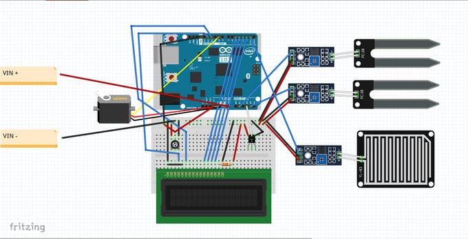
2. (Skip to step 5 if using USB power). Insert batteries into the two battery boxes and tie the positive lead of one box and the negative lead of the other together.
3. Tape the boxes together using electrical tape. Secure the boxes so that the covers of both are attached and the cases of both are attached, and the cover is removable as one piece. Leave slots open for the power switches.
For more detail: An Urban Plant Watering Solution