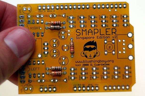
A Smapler is a circuit dedicated to the production of generative sound created by David Cuartielles and Ino Schlaucher from BlushingBoy.org. The Smapler v0002 -aka Singapore edition- is nothing but an Arduino shield to be used for playing funky stereo sounds.

As an extra add-on the Smapler v0002 circuit includes a PS2 connector for you to recycle any kind of PS2 keyboard or mouse as an interface to Arduino.
This Instructable is a guide on how to mount the Smapler v0002 step by step. The circuit comes as a DIY kit that requires between 20 and 50 minutes of your time to mount, depending on your skills.
The design is open source (CC-SA-NC), you can download the schematic, board file, and BOM from here, if you are interested in the original eagle files, you should visit BlushingBoy.org
Step 1: Gear
The tools needed to mount the Smapler are the classic ones for soldering and cutting wires. I am using RoHS soldering tin, a metallic “sponge” to clean the soldering tip, a nice and powerful JBC 26W soldering pen and -just in case- some desoldering bride.
I designed the pads to be extra-wide, what makes soldering very easy. This also makes the PCB more robust to desolder components with the bride.
Step 2: From Resistors to Jumpers in 10 steps
When working with through-hole components the rules for soldering are easy to remember:
– mount components according to their size (smaller first)
– heat the soldering pad with the pen and place the tin on the pad as well, letting it flow and distribute uniformly over the connection
– less is more: be a little conservative with your use of tin, it is enough to have filled the small hole where the component is connected, you don’t need to add a mounting of tin, won’t work better, just the same
1. resistors
2. pushbutton
3. IC sockets
4. sound jack
5. polyester capacitors
6. LEDs
7. electrolytic capacitors
8. PS2 connector
9. pin headers
10. jumpers
Be very careful with the way you connect the electrolytic capacitors. The through-hole caps are always having the (-) negative pin marked, but the PCBs are always showing the (+) positive one.
Step 3: Preparing the Wires
You are going to need some wires to connect potentiometers and switches (as well as whatever other sensors you may be interested in) to your board. I always follow some rules that my dad told me already when I was 9 about how to handle wires:
– if you are planning to connect something to a breadboard, use single-core wires, it will make your life so much easier. This type of wire is weaker, you cannot flex it as much as the other, but it sticks to the breadboard. 0.22mm to 0.28mm are the recommended thicknesses
– if you are making a control panel or something where the components will be moving around a lot, but they won’t be ever disconnected from your board then use multi-core wire. It will never break (or not in the device’s lifetime). Also recommended for more final projects. Again something in the range of 0.2mm is fine
– when using multi-core wires, put some soldering tin on the cable’s tip, just to make it easier to solder to a board or component later on
– after that, solder the wire to the different objects
– if you had e.g. a potentiometer, you should first solder the wires on this component and later hook it to the board. As a matter of fact, you should make all the components first, and then solder them to the Smapler all at once
– when soldering on the components, use some “helping hands” or similar to keep the component fixed, this will avoid accidents. In the picture I am reusing an old milk-carton where I punched the potentiometers to solder the wires one by one
For more detail: Mounting a Smapler v0002 step by step