Have you ever wondered how migratory birds manage to have such an amazing sense of direction despite being so generally clueless? They can sense the Earth’s magnetic field with what is basically a compass built into their body. Wouldn’t it be cool to feel what that’s like?
 The following instructions are loosely based off of a research paper by the (German) OFFIS Institute of Technology, or Oldenburger Forschungs und Entwicklungsinstitut für Informatik-Werkzeuge und Systeme, if you sprechen sie Deutsch. It can be found here:
http://pielot.org/wp-content/uploads/2011/05/Pielot2011-TactileCompass.pdf
Further thanks go to a couple of guides on how to make simple vibration motor and digital compass circuits, respectively. If my explanations aren’t doing it for you, these probably will for their corresponding aspects of the project:
http://learningaboutelectronics.com/Articles/Vibration-motor-circuit.php
http://www.funnyrobotics.com/2011/03/arduino-with-hmc6352-digital-compass.html
Step 1: Materials
So with the citations out of the way, let’s get started. First, you’ll need a bunch of materials. A lot of these are available easily from Sparkfun, but in many cases more cheaply from Jameco or Digikey or something. Total cost is around $150, largely due to the Arduino or similar, compass chip, motors, and appropriate belt. For this project you will need:
1x: Arduino or homemade ATMega microprocessor board. I recommend an Arduino because it’s difficult to fit voltage regulators, a resonator, etc into a small package by yourself. You’ll need a serial interface too, although a USB cable works fine for an Arduino. I used an Arduino Uno with an ATMega 328p. (~$30)
1x: Honeywell HMC6352 compass chip. (~$35)
1x: Belt. Preferably canvas or fabric, of the boating variety. Leather is really no good for this, and the loop buckles won’t get in the way of the circuit elements like a traditional pin-and-hole buckle might. (~$20)
8x: Vibration motors; I used sparkfun’s #8449, they do well @~3V (~$5 ea.)
8x: 1N4001 diode (cheap)
8x: 0.1uF capacitor (cheap)
8x: 2N2222 Transistor (any NPN will probably work.) (cheap)
8x: 1K resistors (1/4W will be fine, microprocessors output low current.) (cheap)
8x: 33-75ish ohm resistors (33 minimum, I used 47 because I had them lying around.) (cheap)
Some: 9V batteries/clips
A Few: Needles & thread (for sewing circuit elements onto the belt once they’re properly soldered.)
Lots: ~22ga wire, electrical tape, solder.
Optional: An on/off switch so that you don’t have to unplug the battery to turn it off.
Note that while I used 8 motors, you can use however many you like; just replace 8 with your number in these instructions, and use 360 / X instead of 45 degree increments in the final code.
Step 2: Build a Motor Assembly
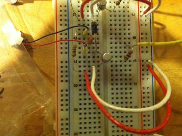
Before starting to work with the actual belt, you’ll probably want to make a prototype using breadboards. The motor assemblies are pretty simple, but you’ll need 8 of them. Each assembly will connect to one of your microprocessor’s digital IO pins, plus a common 5V vcc and ground. You’ll want the assemblies in parallel.
For one assembly, tl;dr refer to the picture. More lengthily, simply connect your desired digital pin to a 1K resistor, and connect that to the B pin of your chosen transistor. The E pin goes to ground, and the C pin is just a bit more complicated. You’ll want it connected to three circuit elements connected in parallel; a diode, a 0.1uF capacitor, and a motor. The motor doesn’t have polarity, and the capacitor is small enough that you don’t have to worry about it. Make sure that the diode’s cathode (the side with the stripe) is facing away from the transistor’s C pin. That’s important, because the diode is there to prevent your motor from drawing too much current and frying the microprocessor. If you do fry your microprocessor, no big deal. Don’t spring for a whole new board, just get another ATMega 168/328 for 5 or 6 bucks and pop it in; sparkfun sells ones with optiboot pre-loaded so you won’t even need a real serial interfacing board. Finally, connect your small-ohm (33-75ish) resistor to the diode’s cathode (and the motor/capacitor by extension), and hook that up to the 5V out. See the picture for details. Refer to your chosen transistor’s data sheet to determine which pin is which.
That’s it! Run a simple test to make sure that everything is hooked up correctly. Note that the motors I recommended have tiny leads, so if you want to plug them into a breadboard you’ll really want to solder a short slip of 22ga wire to each one to ensure that they make consistent contact.
Motor test code (for Arduino or microprocessor board w/ Arduino optiboot):
const int motorPin = <your pin #>;
void setup()
{
pinMode(motorPin, OUTPUT);
}
void loop()
{
// Turn on for 2 seconds, then off for 1 second.
digitalWrite(motorPin, HIGH);
delay(2000);
digitalWrite(motorPin, LOW);
delay(1000);
}
Step 3: Build More Motor Assemblies
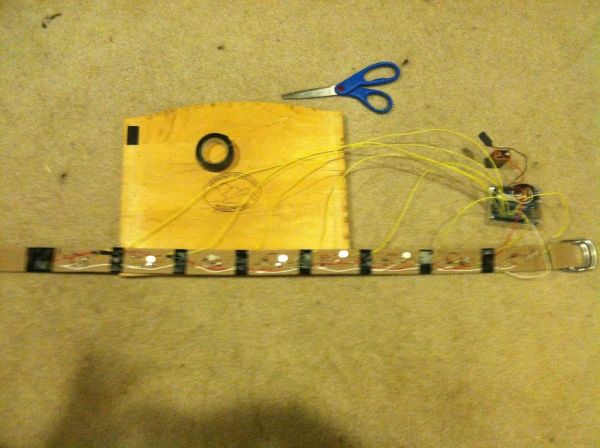
This step is pretty short in writing, but it’ll take a bit of time and patience. Now you need to build 7 more motor assemblies and hook them all up for a total of 8 digital IO pins. Your voltage and ground wires should be shared among the assemblies; just use the +/- columns if you have a breadboard to make it easier on yourself. Once you’re done, it should look something like the picture, except with 8 motors instead of 4. I used two breadboards with 4 on each. I only took a picture of one though, sorry. Each yellow wire should go to its own digital pin on the Arduino, the red/white to 5V/Ground.
I’m pretty sure you could get away with using just one diode/capacitor if you hooked it up right, but this makes the wiring easier and they’re really cheap anyways. Don’t forget to test all of the motors. Since they’re in parallel, one failure won’t cause the whole thing to stop working, which makes troubleshooting very easy. Plug them all in, and just add 7 more pins to the sample code from the previous step. For each one you need to define it, set the mode to output, and tell it to turn on and off:
// I used pins 2-9, you may have different ones.
const int motorPin = 2;
const int motorPin2 = 3;
const int motorPin3 = 4;
const int motorPin4 = 5;
const int motorPin5 = 6;
const int motorPin6 = 7;
const int motorPin7 = 8;
const int motorPin8 = 9;
void setup()
{
pinMode(motorPin, OUTPUT);
pinMode(motorPin2, OUTPUT);
pinMode(motorPin3, OUTPUT);
pinMode(motorPin4, OUTPUT);
pinMode(motorPin5, OUTPUT);
pinMode(motorPin6, OUTPUT);
pinMode(motorPin7, OUTPUT);
pinMode(motorPin8, OUTPUT);
}
void loop()
{
// Turn each pin on for 2 seconds, then off for 1.
digitalWrite(motorPin, HIGH);
digitalWrite(motorPin2, HIGH);
digitalWrite(motorPin3, HIGH);
digitalWrite(motorPin4, HIGH);
digitalWrite(motorPin5, HIGH);
digitalWrite(motorPin6, HIGH);
digitalWrite(motorPin7, HIGH);
digitalWrite(motorPin8, HIGH);
delay(2000);
digitalWrite(motorPin, LOW);
digitalWrite(motorPin2, LOW);
digitalWrite(motorPin3, LOW);
digitalWrite(motorPin4, LOW);
digitalWrite(motorPin5, LOW);
digitalWrite(motorPin6, LOW);
digitalWrite(motorPin7, LOW);
digitalWrite(motorPin8, LOW);
delay(1000);
}
Step 4: Hook Up the Compass
These compass chips are tiny, so soldering the pins can be intimidating. I went through some trial and error here and a burnt finger, but on the upside I can say that if I didn’t fry the chip with my somewhat clumsy soldering, there’s not much chance that you will. So, look at the first picture. This is a good way to solder the leads on. Just stick a wire in the hole, twist it into a little loop, and apply a dab of solder. Works great.
At first, I tried to stick headers on (see image 2). I would have gone with male-to-female, but male-to-male were all I had lying around. Anyways, it did not work well. The solder would not bind the headers to the board. Probably the solder I had just didn’t like the headers I had, but sticking the wires in and soldering them worked so well that I don’t recommend trying to go with headers.
Your compass will have 4 pins; GND, VCC, SDA, SDL. They’re labeled, but for reference to my pictures: white-red-yellow-white = GND-VCC-SDA-SDL. Hook the GND pin up to ground, and the VCC pin to a 3.3V out. This is where having the arduino is nice; you get both 3.3 and 5V regulators onboard, and it can easily run off of a 9V battery (5-20V range, 7-12V recommended), which we’ll get to in a bit. Anyways, hook the SDA pin up to analog pin A4 (20), and the SDL up to pin A5 (21). Note that these chips lose about 2 degrees of accuracy for every 1 degree of tilt and work unreliably beyond 10-15 degrees of tilt, so you’ll want to keep it flat. Load the code at the end of this step onto your microprocessor and open the serial interface while it’s plugged in (ctrl+shift+M in the Arduino interface) to check the output.
In the interest of helping you not repeat my mistakes, I can offer some troubleshooting advice: if, when testing your chip, you get a stream of 0.0 degrees, check your voltage and ground pins’ connections. If you don’t get any output at all, check your SLA and SLD pins. Anyways, here’s the code to test your compass: (see the intro for citation, the digital compass page also has a great image showing better than I could where to connect the logic pins if you’re still confused.)
#include <Wire.h>
void setup()
{
Serial.begin(9600);
Wire.begin();
}
void loop()
{
Wire.beginTransmission(0x21);
Wire.write(“A”);
delay(100);
Wire.requestFrom(0x21, 2);
byte MSB = Wire.read();
byte LSB = Wire.read();
Wire.endTransmission();
float degs = ((MSB << 8) + LSB) / 10;
Serial.print(degs);
Serial.println(” degrees.”);
delay(100);
}
For more detail: How to Make a Tactile Feedback Compass Belt