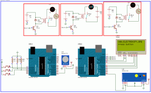
Hello welcome back . This is second part of the wireless home automation . In previous part we have connected home applience with relay and controlled with arduino . In this part we are going to add wireless feature of that device . One arduino is acts as remote controller ie transmitter which transmit input signal from buttons and another arduino receives those signal and switch on home appiliences according to the button pressed . Now first of all connect the circuit as shown in circuit diagram above and upload the hex file after compiling the below code . Upload these code seperately , one code is for transmitter and another for receiver. The short description is shown below the code . You can download whole project from this link wireless home automation . RF module library for proteus can be download from this link Modulo .
Code for Transmitter part
/*

created by prasant

www.electronify.org

you can do what ever you want with this piece of code

*/

const int buttonPin1 = 14;     // the number of the pushbutton pin

const int buttonPin2 = 15;

const int buttonPin3 = 16;

int buttonState1 = 0;         // variable for reading the pushbutton status

int buttonState2 = 0;

int buttonState3 = 0;

void setup(){

pinMode(buttonPin1, INPUT);

pinMode(buttonPin2, INPUT);

pinMode(buttonPin3, INPUT);

Serial.begin(9600);

}

void loop()

{

// read the state of the pushbutton value:

buttonState1 = digitalRead(buttonPin1);

buttonState2=digitalRead(buttonPin2);

buttonState3=digitalRead(buttonPin3);

// check if the pushbutton is pressed.

// if it is, the buttonState is HIGH:

if (buttonState1 == HIGH) {

Serial.write(1);

}

else if (buttonState2 == HIGH) {

Serial.write(2);

}

else if (buttonState3 == HIGH) {

Serial.write(3);

}

else{

Serial.write(4);

}

}
Code for Receiver part
/*

created by prasant

www.electronify.org

you can do what ever you want with this piece of code

*/

#include `

LiquidCrystal lcd(10, 9, 8, 7, 6, 5);

int incomingByte = 0;   // for incoming serial data

const int relayPin1 = 13;      // the number of the relay pin

const int relayPin2 = 12 ;

const int relayPin3 = 11;

void setup()

{

pinMode(relayPin1, OUTPUT);

pinMode(relayPin2,OUTPUT);

pinMode(relayPin3,OUTPUT);

Serial.begin(9600);     // opens serial port, sets data rate to 9600 bps

lcd.begin (20, 4);

lcd.clear ();

lcd.setCursor (0, 0);

lcd.print ("WWW.ELECTRONIFY.ORG");

}

void loop() {

// send data only when you receive data:

if (Serial.available() > 0) {

// read the incoming byte:

incomingByte = Serial.read();

if(incomingByte==1)

{

lcd.setCursor (0, 1);

lcd.print("LAMP1 IS ON ");

digitalWrite(relayPin1, HIGH);

}

else if(incomingByte==2)

{

lcd.setCursor (0, 1);

lcd.print("FAN IS ON ");

digitalWrite(relayPin2, HIGH);

}

else if (incomingByte==3)

{

lcd.setCursor (0, 1);

lcd.print("LAMP2 IS ON ");

digitalWrite(relayPin3, HIGH);

}

else

{

lcd.setCursor (0, 1);

lcd.print("press button ");

digitalWrite(relayPin1, LOW);

digitalWrite(relayPin2, LOW);

digitalWrite(relayPin3, LOW);

}

}

}
Make Arduino Based Home Automation Part-2 (wireless) Using ARDUINO UNO R3 (Schematic Diagram)
Short Description
First of all I want to tell please make a habit of reading arduino official documentation . In this project I have referenced from aduino serial communication from this link . The code is very simple .
First of all the transmitter transmit a secret code to the next arduino according to the button pressed . Let’s say we are transmitting 1 if button 1 is pressed and similarly 2 if button 2 is pressed and so on using the function serial.write(int) . Then at the receiver side the second arduino detects these transmitted number comming from RF module and receive those numbers and take action according to the received number . Let’s say first button 1 is pressed at transmitter side and 1 is transmitted and the second microcontroller detect 1 and it thinks to turn on 1st relay . And similary if 2 is received then it turns on 2nd relay and so on . Using this simple concept we are finally able to make a wireless home automation . If you didnot understand what i mean please read these as shown in link below step by step and you will finally know what i meanRemote controlled Home automation without using microcontroller (Part-1)
- Remote controlled Home automation without using microcontroller (Part-2)
- Remote controlled Home automation without using microcontroller (Part-1)
- AVR atmega32 chip to chip serial communication

