Finalized Prototype
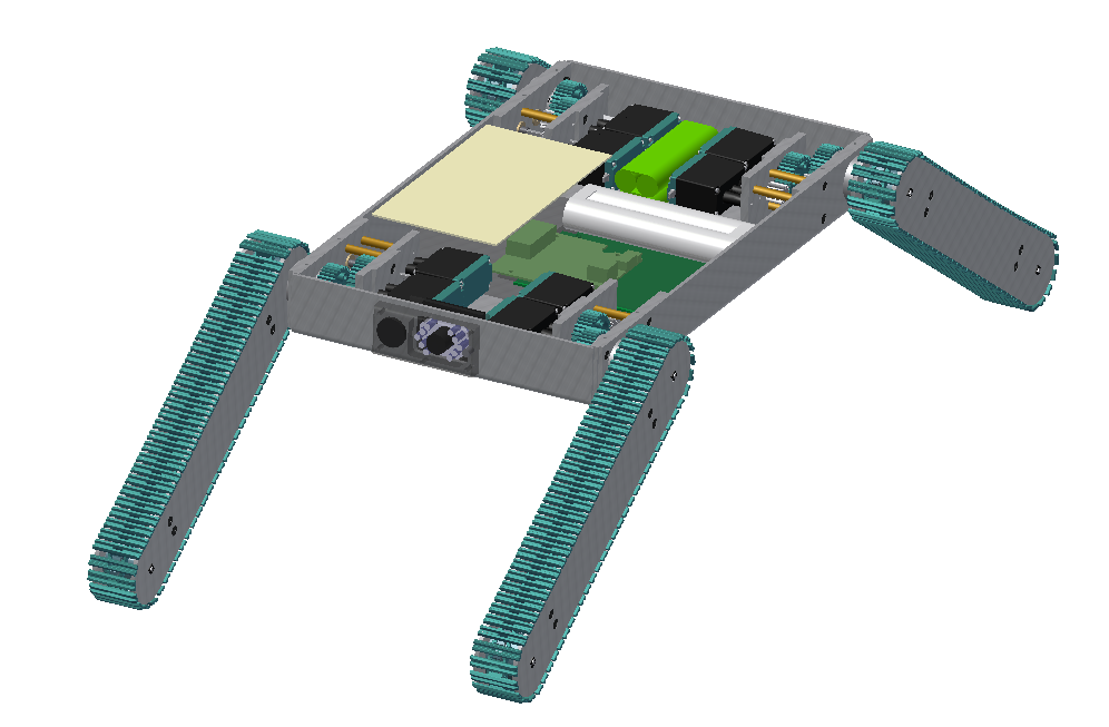
Shown below is the finalized prototype. The purpose of the prototype was to demonstrate the feasibility of a small, highly maneuverable search and rescue robot. As such, the completed prototype was successful. Capabilities include a ground speed of 10 inches per second, battery life of 50 minutes, wireless range of between 50 and 150 feet (depending on interference), weight of 14.5 pounds and the ability to climb stairs. The prototype is also capable of crossing a gap of at least 10 inches and of climbing a 21 inch tall ramp angled at 49 degrees from horizontal. It provides the operator with a color video feed (with nighttime illumination) and two-way audio communication.
Arm Rotation Sensors
The robot also features 4 arm position sensors to indicate the orientation of each leg relative to the body. The sensors are designed similarly to potentiometers with a C-shaped piece of resistive paper. As the arm rotates, it makes contact between the resistive paper and the output terminal. The output voltage is measured with the Arduino’s analog inputs.
First fully wireless test
This was the second major test of the prototype, the first test done entirely without external connections. Again, the laptop used to send commands and view the camera feed (as well as send and receive audio) is not shown. This test brought to light yet more software and hardware issues, which are being addressed.
Line of sight wireless range test
With the robot set up in the configuration shown in the above video, the team tested the line of sight wireless range. The team was able to remain in control of the robot at a distance of approximately 160 ft. More tests are planned to analyze the impact of structural interference.
First full motor test with wireless control
This was the first major test of the prototype. 6 of 8 motors were connected (all except front left rotation and translation). Some software bugs were discovered in the test and are being fixed. Not shown is the laptop connected wirelessly to the robot which is being used to control the motors. Also note that the camera is working with a video feed being sent to the desktop computer shown in the video.
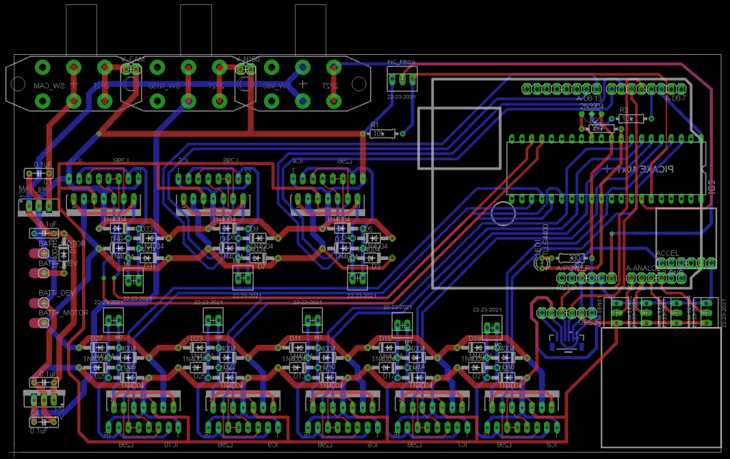
Shown above is the motor controller board connected to an Arduino microcontroller. The board has an accelerometer (red square in first image), a connector for a GPS (small bottom left connector), eight individually controllable motor drivers and power regulation circuitry. Most of the motor drivers are driven by an additional output expanding IC.
The motor drivers and voltage regulators are collinear so that two heat sinks may be attached. Also shown is an ethernet cable to connect the arduino to the ethernet shield.
For more detail: Highly maneuverable search and rescue robot


