Overview
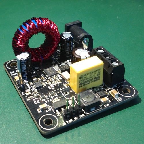
This project is a HVPSU (High-Voltage Power Supply) that generates up to 220V from a 12V input. In addition to that, it also provides 2*Vout (so, up to 440V, for dekatrons), and two outputs for powering digital logic: 5V and 3.3V. The primary HV boost circuit reaches 88% efficiency when going from 12V to 185V at 55mA, with a 3% output ripple.
I designed it because I couldn’t find anything that would make sense for my Nixie projects. There are plenty of tiny power supply modules available on eBay, but most of them end up being impractical: no 3.3V (for my microcontroller) and 5V (for my 74141 nixie drivers), no mounting holes, no >400V output for powering dekatrons. Some supplies make a token gesture towards practicality by sticking a 7805 on the same board, but you quickly find out that the current draw of 6×74141 is enough to require a large heat sink on a 12V-powered 7805 (one 74141 consumes 12.5mA!). This means that instead of a single-board power supply you end up routing your input power all over the place, implementing your power supply in several places.
I wanted to have something versatile enough so that I could use it in a number of projects: with nixies, dekatrons, other tubes, VFDs, phone ringers, etc. I also wanted it to fit on a 5x5cm PCB, so that I can order 10 PCBs for $10 at iteadstudio.
The version I’m posting online is not perfect, but works quite well in a number of my projects. I decided I’d rather publish it as it is now rather than keep it locked forever.
The circuit and PCB you see are the result of multiple iterations. I started out with a design based on MAX1771, which turned out to have stability problems, mostly due to EMI on the feedback pin. I then went through seven board designs, trying to make it work. I ended up with a design that mostly worked, but exhibited uncontrolled behavior in some conditions (load transients, overcurrent, EMI). I finally got tired of the MAX1771 chip and decided to look for another solution.
I chose the TPS40210 from Texas Instruments, which seemed to be a solid performer in high-voltage boost applications, was easily available, not too expensive. The existence of an automotive-grade version also means that the chip won’t disappear anytime soon. I went through three board revisions with the TPS40210, which were mostly about shrinking the design and adding the TPS62160 buck converter instead of a 7805 to produce 5V.
n the process I learned a lot and discovered that there is a lot of stuff about boost converters that I didn’t even know I didn’t know. Here are a few examples:
- Loop stability: I had no idea why it was an issue or how to design loop compensation (TI’s SwitcherPro is really helpful).
- CCM vs DCM and transitions inbetween.
- Current-mode control sub-harmonic instability in continuous conduction mode.
- RC snubber: do you know about parasitic ringing on the switching node? That ringing that your scope probably won’t show, because it’s above 500MHz?
I now know slightly more, but the circuit certainly isn’t perfect. I don’t even have the equipment to measure some of its properties, so I have to leave it as it is.
There are two principal reasons for making this available as an open-hardware project:
- I learned a lot by studying the designs of others, and I felt I owe the community something in return (Nick de Smith’s Nixie HV Switching PSU page was especially helpful).
- Most Nixie PSU designs I saw online are based on the MAX1771, and apart from people hacking crude 555 supplies, there seems to be little variation. I thought an alternative should be out there.
Features:
- Generates 4 voltages from 12V input:
- Vout: up to 220V at up to 80mA, 2-3% voltage ripple
- 2*Vout (optional): up to 440V at up to 30mA
- 5V at up to 1A at ~85% efficiency for older digital logic such as 74141 Nixie drivers (compare to about 40% efficiency if a 7805 is used)
- 3.3V for modern digital logic (microcontrollers, etc)
- High-voltage DC-DC converter can be shut down digitally to save power
- Can be used with many different power inductors, depending on desired output power:
- SMD 12.5×12.5mm
- THT vertical barrel type, rasters of 5mm, 8mm, 11mm
- THT vertical toroidal type, 8mm raster, up to 23.5x11mm
- Known & fixed switching frequency (50kHz)
- Nominal input is 12V, can be up to 16V
- Safety features: overcurrent protection, thermal shutdown, slow-start.
Downloads, Release Notes and Licensing
- Schematic as a PDF file
- A zipfile containing the schematic, PCB, Eagle .sch and .brd files, and Gerbers prepared for manufacturing at iteadstudio.
- There is also a partlist, as generated by Eagle. Not a real BOM, but at least you’ll know what to need and what resistor sizes to use.
Version 2.2 is what I use in all my projects. Version 2.3 has several tiny fixes: adjusted position of mounting holes, added comments in the schematic, but is otherwise identical to 2.2.
I wanted to pick an Open-Source Hardware license, but couldn’t find one. There is lots of talk about Open-Source Hardware, but when you actually want to open-source something, it turns out it isn’t easy.
For more detail: High Voltage Power Supply for Nixie Tube Projects