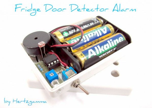
Has it ever happened to you to go to the fridge and discover that its door is slightly opened … and probably most your food went to the trash … Ghhhrr that jammed door that needs an extra push to make it close properly ……. This instructables will show you how to make an alarm system that will beep a buzzer if you leave the fridge door opened for a long time to remind to you to close the door. All new fridges on the market have this option built in, but some may want to upgrade their old fridges.
- The Fridge Door Detector Alarm is easy to make – uses only 8 components including the batteries!
- Easy to set to your preferences for the time that the door is left opened – fully customizable!
- Cheap – less than 5kg potatos.
- Easy to install – installation means sticking a small box inside your fridge using sticky tape!
- Easy to maintain – change batteries just every four-five months!
- Encourages thinking and logic problem solving for the young electricians that will try to make it!
- Finally – saves electricity costs if you forget the door opened for a long time.
Update History:
- 1st Oct 2012 – Added several schematics in steps 4 and 5.
- 4th Oct 2012 – Visually changed the code appearance in step 3.
- 7th Oct 2012 – Instructions made more clear in step 3.
- NEW: 8th Oct 2012 – Major changes in the ATtiny85 code: better power mode – enabled power save mode to reduce consumption. New code in step 3.
- NEW: 9th Oct 2012 – Added description for how to set the circuit sensitivity up. See step 7.
Step 1: The Idea
What the Fridge Door Detector Alarm does is to detect whether there is some ambient light in the food compartment of your fridge or freezer. This happens when you open the door and the Fridge Door Detector Alarm system senses some light that may be coming from the bulb light in the fridge or from the door opening itself. The Brain I use an ATtiny85 microcontroller which is easy to program with an Arduino if you have one 😉 Than you can write the code that will suit your needs perfectly – for example one may want to hear the buzzer 2- seconds after opening the door … or maybe 45 or 2 minutes – you decide! Using a microcontroler minimises the use of external elements which saves you time and cost! The Components
- ATtiny85 microcontroller
- Arduino Uno
- Prototyping board + wires
- Buzzer
- Switch
- Plastic box
- 180 kOhms resistor
- 0-100 kOhms variable resistor
- LDR – light dependent resistor
- Batteries
- Empty PCB to solder the schematic
- Board holder for the ATtiny
The Tools
- Soldering iron
- Double sided sticky tape
- Cable cutters and knife
Step 2: ATtiny85 Programming Hardware Connections
As shown on the diagram: ATtiny pin <> Arduino Uno pin 1 <> 10 5 <> 11 6 <> 12 7 <> 13 4 <> GND 8 <> 5V
Step 3: Programming Software Development
You can follow my steps or alternatively here is a link that will show you how to connect the ATtiny to the Arduino: http://hlt.media.mit.edu/?p=1695 Steps to connect ATtiny85 to Arduino Uno for programming:
- Download this file: https://github.com/damellis/attiny/zipball/Arduino1
- Unzip and put the “attiny” folder in the “hardware” folder where tha Arduino is installed on your PC. The path looks like this: Documents > Arduino > hardware > attiny> (Other downloaded files… etc)
- Start the Arduino Application and open the ArduinoISP from the FIle>Examples menu
- Upload the sketch to the Arduino Uno.
- Now change the following settings:
- Check the ATtiny85 (8 Mhz) checkbox in the Tools > Board menu.
- Check the: “Arduino as ISP” in the Tools > Programmer menu.
I have uploaded two versions of the software. The first works on Arduino Uno only and this is because I made the experimental circuit on the Arduino firstly. See the pictures for the camponent arangement that I made. You have a choice of lots of pins for the inputs and outputs, so it depends on you how you name them in the coding. I used pin A0 for the analogue input from the LDR and then I have pins 2, 3 and 4 for the rest of the circuit. YOU can skip connecting all components to the Arduino if you prefer. There is no need to do it, you can go straight on the ATtiny programming. Basic software understanding – READ THIS TO SEE HOW THE SOFTWARE WORKS The basic program concept is that every second there is a pin that powers the LDR and some current flows through it and the variable resistor. Then the middle point between the LDR and the variable resistor is measured from the microcontroller and the measurement (voltage between 0 and 5 volts) is compared to a set value (2.5 volts in my case) and a logic decision is made. In one case nothing happens and the measurement continues on and on. In the other case an LED lights up to show that the door has been opened. At the same time a timer starts counting seconds and if it reaches the set number of seconds (i.e. 10 seconds), then a beep sounds until the door is closed. While seconds are counted down and the beeps sound, measurements are also taken to see what is the situation with the door. We will be using an Arduinho Uno to program the ATtiny85. For more detail: Fridge Door Detector Alarm

