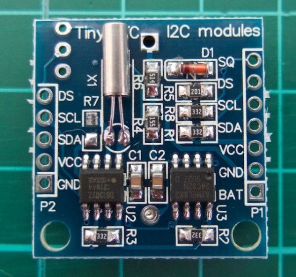
We keep getting requests on how to use DS1307 and DS3231 real-time clock modules with Arduino from various sources – so this is the first of a two part tutorial on how to use them. For this Arduino tutorial we have two real-time clock modules to use, one based on the Maxim DS1307:
There are two main differences between the ICs on the real-time clock modules, which is the accuracy of the time-keeping. The DS1307 used in the first module works very well, however the external temperature can affect the frequency of the oscillator circuit which drives the DS1307’s internal counter.
This may sound like a problem, however will usually result with the clock being off by around five or so minutes per month. The DS3231 is much more accurate, as it has an internal oscillator which isn’t affected by external factors – and thus is accurate down to a few minutes per year at the most. If you have a DS1307 module- don’t feel bad, it’s still a great value board and will serve you well.
With both of the modules, a backup battery is installed when you receive them from Tronixlabs, however these are an inexpensive variety and shouldn’t be relied on for more than twelve months. If you’re going to install the module in a more permanent project, its’ a good idea to buy a new CR2023 battery and fit it to the module.
Along with keeping track of the time and date, these modules also have a small EEPROM, an alarm function (DS3231 only) and the ability to generate a square-wave of various frequencies – all of which will be the subject of a second tutorial.
Connecting your module to an Arduino
Both modules use the I2C bus, which makes connection very easy. If you’re not sure about the I2C bus and Arduino, check out the I2C tutorials (chapters 20 and 21), or review chapter seventeen of my book “Arduino Workshop“.
Moving on – first you will need to identify which pins on your Arduino or compatible boards are used for the I2C bus – these will be knows as SDA (or data) and SCL (or clock). On Arduino Uno or compatible boards, these pins are A4 and A5 for data and clock:
For more detail: Using DS1307 and DS3231 real-time clock modules with Arduino