Forward:
This instructable was originally posted at http://www.instructables.com/id/How-to-make-LED-Fader-using-Digispark/
My students and I developed it into this exemplar, for which they received a very good mark.

Viewing the following video may leave you with a sense of too much too fast. Please continue to read this Instructable which documents my students’ Tanner and Amanda’s culminating math project. The concept of the project was to get my students to extend obtuse angles to beyond simple trigonometry, and solving triangles. Instead I wanted them to enjoy the experience of some authentic learning as they explored an application of the sine function that isn’t found in their textbook.
Step 1: Which processor board to Use?
The Digispark
The Digispark is one of the smallest and cheapest USB Arduino processors available today. It is bassed on the ATTiny85 processor. The Digispark is very easy to program using a version of the Arduino IDE tailored to the ATTiny 85 processor. The most significant difference from boards such as the Arduino Uno is pins assignments. The Digispark only has 6 data pins and three power pins as opposed to the Uno’s 32. You can learn more about the Digispark at http://digistump.com. In this project we use pins 0, 1, and 4 as well as the GND pin.
Step 2: Pulse Width Modulation
What is PWM?
Processor boards such as the Digispark can modulate the power sent to an LED giving the effect of fading while still providing a digital on or off signal. The process is known as Pulse Width Modulation or PWM. PWM switches on for a percentage of a duty cycle and off for the remainder. In a 12 volt circuit, the effect of 6 volts can be achieved if the power is switched on and off rapidly 50% of the time. This avoids heat issues that would be associated with using a rheostat or potentiometer. PMW values extend from 0 to 255, representing 0% to 100%.duty cycle. A PWM value of 64 corresponds to a 25% (0.25*255) duty cycle or 1/4 power. Similarly a PWM value of 191 corresponds to a duty cycle of 75% (0.75*255) or 3/4 power.
Now that we understand what PWM is, how do we generate a series of values that will give a subtle ebbing of LED intensity.
Step 3: The Sine Wave Function
Three Waves are Better than One
The basic sine wave function generates numbers from -1 to 1. How do we modify the basic function for use as a PWM number generator?
general form:
y = a*sin(b*x + c) + d
Where
b changes the period (how long the wave is)
c causes a phase shift along the x axis
d raises or lowers the wave along the y axis
The sine wave produces numbers between -1 and +1. This causes an issue because PWM values can not be negative. The first change we need to make is to add 1 by substituting 1 for d in the formula. y=a*sin(b*x+c)+1 will give us values between 0 and 2.
Next we needed to increase the amplitude to produce our maximum PWM value of 255. As it stands the max value is 2. Therefore 255/2= 127.5. The PWM needs to be an integer so we settle on 127 which will gives us a max of 254. Now the formula looks like this:
y=127*(sin(b*x+c)+1) note the additional brackets.
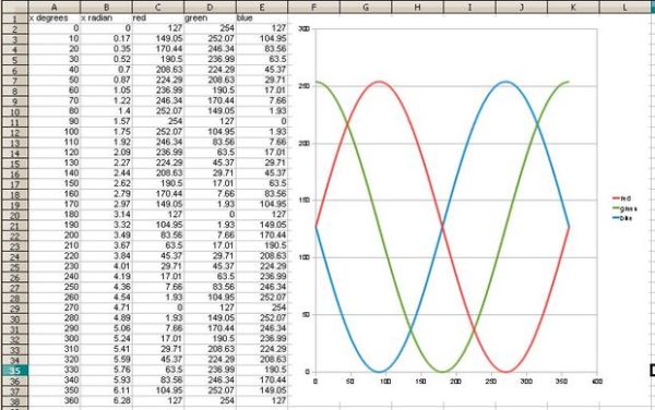
We have three LEDs which we want to interact together to give subtle shifts in additive colour values. Therefore we had to use a phase shift for each colour. This where it gets tricky for us. Computers use radians not degrees. Therefore the phase shift had to be expressed in radians. It turns out the conversion is simple. 90° = 90/180*PI radians or 1/2*PI radians. A 270° phase shift would require 3/2*PI radians. If we do not alter the period we now have three functions, one for each colour of our LED
green=127*(sin(x+1/2*PI)+1)
blue=127*(sin(x+3/2*PI)+1)
Step 4: Arduino Program
Arduinos are simple to program and the IDE is free under the CC license. The Digispark uses a modified version for the Arduino IDE which included special libraries to reflect the change in pin assignments etc. The Digispark Arduino IDE is available at http://digistump.com/wiki/digispark/tutorials/basics and http://digistump.com/wiki/digispark
ARDUINO BOARD IDE 1.0.3 CODE

//Declare all variables

int LED1; // these variables will be used to hold the led PWM values
int LED2;
int LED3;

int p0=0; /* these variables will assign a variable to receive PWM values and pass them to their respective pins*/
int p1=1;
int p4=4;

float x;
/*this a variable that will receive the angle value from variable i. This value is converted to radians in the sine function and will be used to generate the PWM values */

float r; // these variables will receive the PWM values calculated by the three sine functions
float g;
float b;

// the setup routine runs once when you press reset;

void setup() {

// initialize the digitals pin as an output.
pinMode(p0, OUTPUT); //sets up pin 0 for pwm
pinMode(p1, OUTPUT); //sets up pin 1 for pwm
pinMode(p4, OUTPUT); //sets up pin 4 for pwm

/*Run a diagnostic test that will verify that each colour of LED is working.
Turns on the LEDs consecutively with a delay of one second between each*/

digitalWrite(p0, HIGH);
delay(1000);
digitalWrite(p1, HIGH);
delay(1000);
digitalWrite(p4, HIGH);
delay(1000);

//Turn off LEDs one after the other with a one second deleay between each

digitalWrite(p0, LOW);
delay(1000);
digitalWrite(p1, LOW);
delay(1000);
digitalWrite(p4, LOW);
delay(1000);
}

// the loop routine runs over and over again forever:
void loop() {

/*The for loop generates a value for a variable i which corresponds to 0 to 360 degrees. I is increased by 1 with each iteration.  It is later converted to radians within the loop. Once i reaches 360 it resets back to 0. This establishes the periodic behaviour of the sine fun functions*/

for (int i=0; i<360; i++)
{

//convert i into a floating point variable that can be used with PI
x=float(i);

/* to calculate r,g,b the sine function is modified to increase amplitute (127*) to create a phase shift (x+1/2*PI) and (x+3/2*PI) finally the sine wave is raised to illiminate negative values below zero by adding 1*/

r=127*(sin(x/180*PI)+1);
g=127*(sin(x/180*PI+3/2*PI)+1);
b=127*(sin(x/180*PI+0.5*PI)+1);

//convert flaot r,g,b to integers that can be assigned to LED PWM numbers

LED1= int(r);
LED2= int(g);
LED3= int(b);

//write LED levels to p0, p1, p4 (ASSIGN PWM values to LEDs)

analogWrite (p0,LED1);
analogWrite (p1,LED2);
analogWrite (p4,LED3);

//wait for 1/100 of a second

delay(100);
}
}
In this project a number from 0-255 is used to represent 0%-100% duty cycle (brightness), sine function is used to generate it. Digispark uses sine function to generate the PWM (pulse width modulation). We convert the radians to degree’s for the red, green, blue cycles. This is used to change the language for the computer to understand. One small difference from regular Arduino boards and the Digispark is that the program compiler prompts you to attach the Digispark when it is ready to upload. If you leave it connected you will get a compiler error.
For more detail: Digispark RGB LED Fader