Summary of Controlling a Servo with Arduino
This article provides a basic guide to controlling a servo motor using an Arduino board with PWM signals. It explains connecting a servo's power, ground, and control wires to the Arduino, uploading a sample sweep sketch to move the servo between 0 and 180 degrees, and then adding a potentiometer to control the servo position manually. The setup involves using common components like a servo motor, potentiometer, and Arduino with the Arduino Servo library, demonstrating a simple interactive servo control circuit.
Parts used in the Servo Control with Arduino Project:
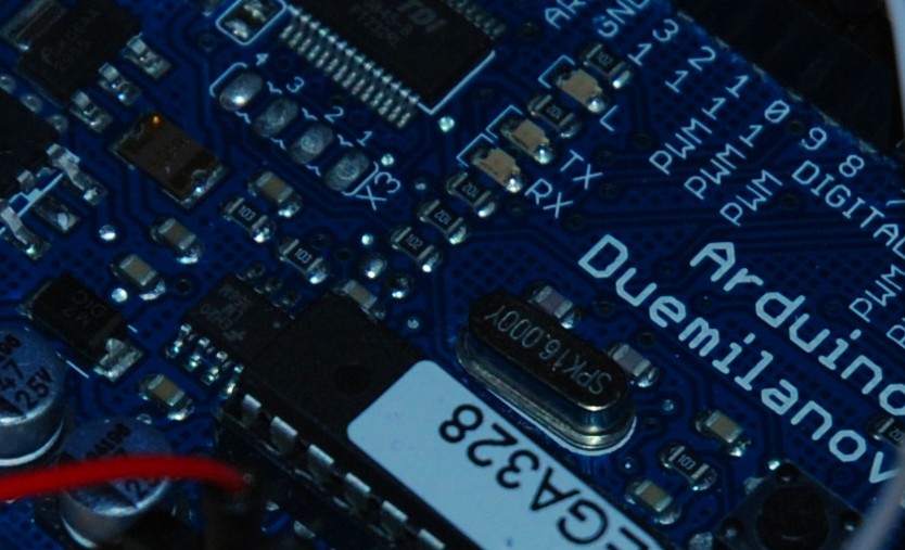
- Arduino Board (Duemilanova ATMEGA328)
- Arduino Sketch Software (version 0015)
- Arduino Servo Library
- Servo Motor (Futuba S3113)
- Potentiometer
- Breadboard
- Connector Wires
Very simple basics of building a circuit to control a servo using Arduino and PWM
For this you will need:
Arduino Board – I’m using a Duemilanova ATMEGA328
Arduino Sketch software – I’m using version 0015
Arduino Servo Library found here save it to lib/targets/libraries if you don’t already have it
A Servo that requires no more than a 5V supply I’m using a Futuba S3113
A Potentiometer (A dimmer switch)
Breadboard & Connector wires
Previously used Arduino, at least to do basic blinking LED
So we’re going to assume that you’ve already used the sketch software and uploaded at least your first sketch to the Arduino board.
First lets start with just connecting a servo to the board.
I’ve used some connecting wires to connect between the servo pins to the ardunio board. The red wire is positive, the black negative/ground and the white is what relays the feedback/instructions.
The red wire goes to the +5v pin, the black goes to the GND pin on the Arduino and I’m going to put the white wire to pin 9 PWM.
Thats it! So now you just need to upload the code below to the board. You can use this example sketch also provided with Arduino
Arduino Servo Sketch
// Sweep
// by BARRAGAN
#include //include the servo libary
Servo myservo; // create servo object to control a servo
// a maximum of eight servo objects can be created
int pos = 0; // variable to store the servo position
void setup()
{
myservo.attach(9); // attaches the servo on pin 9 to the servo object
}
void loop()
{
for(pos = 0; pos < 180; pos += 1) // goes from 0 degrees to 180 degrees
{ // in steps of 1 degree
myservo.write(pos); // tell servo to go to position in variable ‘pos’
delay(15); // waits 15ms for the servo to reach the position
}
for(pos = 180; pos>=1; pos-=1) // goes from 180 degrees to 0 degrees
{
myservo.write(pos); // tell servo to go to position in variable ‘pos’
delay(15); // waits 15ms for the servo to reach the position
}
}
So you should see the servo move!
If you got this far lets now add in a potentiometer to control the servo, so when you turn the potentiometer it will turn the servo.
The potentiometer, it has 3 pins like the servo, the outside pins are for the supply (+/-) and the middle pin is for the control/ feedback.
First lets setup the breadboard for the circuit, all red wires are positive, black are negative and the 2 white wires are the feedback to the Arduino chip.
Here’s the final setup I did below:
Near the start of the circuit I’ll add the potentiometer and at the end of the cicuit I’ll put the servo.
For more detail: Controlling a Servo with Arduino