Summary of Build Your Own Sourcemeter Using Arduino
This article details a DIY USB-powered sourcemeter using an Arduino Nano and Processing GUI to measure solar cell IV characteristics. It outlines the circuit design involving DACs, op-amps, and precision resistors for voltage sweeping and current measurement. The guide includes a parts list, firmware upload instructions via Arduino IDE, and steps to run the Processing-based user interface on various operating systems.
Parts used in the USB-Powered Sourcemeter:
- Printed Circuit Board
- Arduino Nano Microcontroller
- Microchip MCP4822 dual-channel Digital-to-Analog Converter
- Texas Instruments TLV4110 Operational Amplifier (2)
- Ohmite WNBR10FET 0.1 ohm +/- 1%, 1W resistor
- Panasonic ERO-S2PHF3000 300 ohm +/- 1%, 0.25W resistor
- Panasonic ERO-S2PHF3001 3k +/- 1%, 0.25W resistor
- Panasonic ERO-S2PHF1202 12k +/- 1%, 0.25W resistor
- Panasonic ERO-S2pHF3002 30k +/- 1%, 0.25W resistor
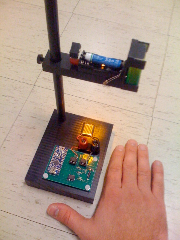
This is an explanation and set of building plans for a USB-powered sourcemeter with a personal computer interface. The sourcemeter uses an open-source Arduino microprocessor and the user interface uses the open-source Processing environment. The sourcemeter was designed as a homemade current-voltage (IV) tester to measure the IV characteristics of a solar cell by sweeping applied voltage across the device and measuring the current at a series of voltages, but it could be applied to other measurement tasks.
For questions, please contact David Berney Needleman (dbn AT mit DOT edu) or Rupak Chakraborty (rupak AT mit DOT edu).
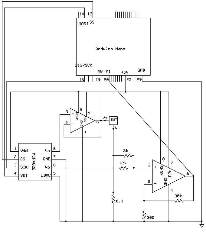
The basic circuit for the sourcemeter is as follows:
-
- The Arduino Nano microcontroller (Arduino) uses 3 digital output pins to control a dual-channel digital-to-analog converter (DAC).
- This DAC programs two voltages:
- The first voltage is applied across the device under test (DUT), in our case a solar cell. In order to insulate the DAC from the current through the DUT, a buffer amplifier (in our case an operational amplifier wired for unity gain) is placed between them. The voltage across the DUT is also split off and read at one of the Arduino’s analog input pins.
- The second voltage is used as part of a summing amplifier to make our current measurement readable by the Arduino (details below).
- The current through the DUT is converted to a voltage by dropping it across a 0.1 ohm resistor, so that it can be read at one of the Arduino’s analog input pins. This negative terminal of the DUT and the second voltage output from the DAC, each in series with a resistor, are both wired to the positive terminal of an op amp configured as a summing amplifier. The resistor values in our circuit were chosen to convert our expected current range (+/-30mA dropped across a 0.1 ohm yields +/-3mV by Ohm’s Law) to the internal reference voltage for the Arduino (0V to 1.1V). For a good explanation of using a summing amplifier for this type of conversion, see http://masteringelectronicsdesign.com/design-a-bipolar-to-unipolar-converter/. Note that it is important that these resistance values be fairly precise. Variations will result in the scaling and zero of the current measurement being off slightly. This discrepancy can be corrected in the currentReadingmA function in the Arduino code.
Circuit Diagram (download in .sch format here).
*Note: To put a solar cell in forward bias, the p-type side would be connected to the V+ terminal in this diagram. For reverse bias, the n-type side would be connected to the V+ terminal.
Parts List: These were used for our implementation. Substitutions (e.g., to change the current range or due to availability) should be fine though they may require small modifications to the software.
- Printed Circuit Board
- Arduino Nano Microcontroller
- Microchip MCP4822 dual-channel Digital-to-Analog Converter
- Texas Instruments TLV4110 Operational Amplifier (2)
- Ohmite WNBR10FET 0.1 ohm +/- 1%, 1W resistor
- Panasonic ERO-S2PHF3000 300 ohm +/- 1%, 0.25W resistor
- Panasonic ERO-S2PHF3001 3k +/- 1%, 0.25W resistor
- Panasonic ERO-S2PHF1202 12k +/- 1%, 0.25W resistor
- Panasonic ERO-S2pHF3002 30k +/- 1%, 0.25W resistor
Firmware and GUI Software
*Note: these instructions assume that you have the Arduino IDE and Arduino driver installed. See the Arduino help pages to get started.
Download and extract the IVy zip file locally. Navigate to “source” > “IVy_arduino”. Open the file “IVy_arduino.pde” with the Arduino IDE. Compile the code and upload it to the Arduino board.
Once the Arduino board is loaded, use the Processing application to run the board. For convenience, the Processing code is already compiled and exported to an executable format for Linux 32/64-bit, Mac OSX, and Windows 32/64-bit. These are located in the “application” folder. Within the “application” folder, navigate to the folder which matches your platform. If the 64-bit version does not work on your 64-bit system, use the 32-bit version.
Make sure the Arduino board is connected to your computer, and then run the executable. A window showing the IVy user interface should open. Under the “Connection” section, there is a drop down menu displaying all available serial COM ports. Select the COM port that the Arduino board is using, and then click the “Connect” button. The status bar at the bottom should display “Connected” if the connection was successful. As long as the IVy interface stays open and the Arduino board remains physically connected to the computer via USB, this step does not need to be repeated.
For more detail: Build Your Own Sourcemeter Using Arduino
- What is the primary purpose of this sourcemeter?
It was designed as a homemade current-voltage tester to measure the IV characteristics of a solar cell. - How does the device convert current into a readable voltage?
The current through the DUT is converted to a voltage by dropping it across a 0.1 ohm resistor. - Which microprocessor controls the digital-to-analog converter?
The Arduino Nano microcontroller uses 3 digital output pins to control the dual-channel DAC. - Can this project be applied to tasks other than solar cells?
Yes, while designed for solar cells, it could be applied to other measurement tasks. - What software environment is used for the user interface?
The user interface uses the open-source Processing environment. - How do you connect the Processing application to the hardware?
You must select the correct serial COM port from the drop down menu and click the Connect button. - Are substitutions allowed for the listed components?
Substitutions are fine though they may require small modifications to the software. - Why must the resistance values be precise?
Variations will result in the scaling and zero of the current measurement being off slightly.