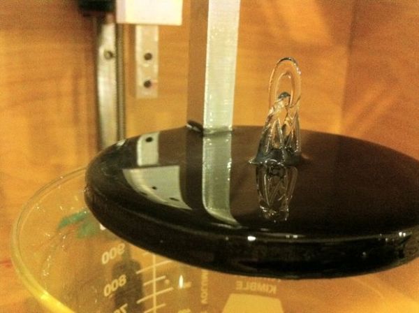
Here is how to make a Stereolithography 3D Printer. It is still a bit of a work in progress but so far it is working pretty well. This is mainly an experiment which started as a Delta Robot Stereolithography Printer but ended as a more traditional Cartesian Stereolithography Printer.
Stereolithography (SL or SLA from Stereolithography Apparatus) is an additive manufacturing process using a vat of liquid UV-curable photopolymer “resin” and a UV laser to build parts one layer at a time. On each layer, the laser beam traces a cross-section pattern of the part onto the surface of the liquid resin. Exposure to the UV laser light cures, solidifies the pattern traced on the resin and adheres it to the layer below.
I have wanted a 3D Printer for a while now and there are some very reasonably priced kits available like the Makerbot, Ultimaker and the RepRap project. I could have just bought a kit and started printing things but at the time I had not seen great resolution or print quality from those. I started looking around at the other 3D printing technologies and found SLA made some amazing quality prints, so I decided to try making my own. Since I started this a while back those projects have come a long way and they can make some beautiful prints now. There are also people working on a UV resin and DLP projector 3D printer which is showing promise.
I decided to enter this in the Epilog Challenge Contest because I could really use a laser cutter 🙂 I also have some ideas how to redesign this project, for creation on a laser cutter. I wouldn’t mind making kits for people if I had one.
Something to keep in mind is the current cost of commercially available UV/Visible resins. 1 Liter is about $200 – $250 so compared to ABS or PLA for the plastic extrusion printers it is about 4 – 5 times more as far as I can tell. There are other types of resin that are cheaper but I do not know how well they will work.
Since I wasn’t really sure if this was going to be a viable method of creating 3D objects, this was a fairly cheap and quickly designed project. I have a small Taig CNC Mill for cutting metal so the custom parts are made of scrap aluminum I had laying around. You can probably use wood and maybe even hand cut the parts if you are careful.
This project is Open Source Hardware.
Step 1: Materials, Tools and Safety
General Parts
3 – 16″ x 171/2″ x 3/4″ Plywood for the back and sides of the case
2 – 16″ x 16″ x 3/4″ Plywood for the top and bottom of the case
24 – #6 x 3″ wood screws and washers
4 – Rubber Stoppers 1 7/8″ x 1 3/4″
4 – 1/4-20 x 2 1/2″ Bolts
8 – 1/4-20 Nuts and washers
1 – 4″ x 4″ x 1/4″ Black Acetal sheet (Delrin)
1 – 1 Liter Beaker
Linear Rail and Blocks from Automation Overstock
4 – AG Linear Rail 15mm x 200mm
2 – 15mm Bearing Block, 2 Bolt Flange
2 – 15mm Bearing Block, 4 Bolt Flange
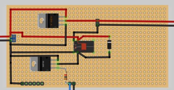
Electronics Parts from Sparkfun and others
6 – microswitches with roller
3 – ROB-09238 Stepper Motors
3 – EasyDriver Stepper Drivers (Pololu drivers should work too)
3 – Polarized Connectors 4-Pin housing
3 – Polarized Connectors 4-Pin Header
2 – 6 pin female headers
2 – DC Barrel Jack Adapters – Female
1 – Sanguino (Arduino Mega would work too with code modifications)
1 – 5V FTDI USB Cable
1 – Omron G5V-1 Relay
1 – LD33V 3.3V Voltage Regulator
2 – 9V 500ma or higher Power Supplies (could use one but they are cheap)
1 – 12V – 24V 2000ma or higher Power Supply (for Stepper Motors)
1 – TIP120 Transistor
1 – 1K Resistor
1 – Protection Diode such as 1N4148
2 – 2 pin screw terminals
Various Male and female .1″ headers, wire and protoboard big enough to fit everything
Leadscrew from McMaster-Carr
1 – 1018 Carbon Steel Precision Acme Threaded Rod, 1/4″-16 Size, 3′ Length
Leadnuts from DumpsterCNC
3 – Acme 1/4″-16 (1 Start) Leadnuts Square flange 4 hole
3 – Acme 1/4″-16 (1 Start) Couplers 5mm Bore
Laser parts from Aixiz
1 – Aixiz blue laser glass lens
1 – Aixiz 405nm violet laser 20mW
1 – Iris Diaphragm, Zero Aperture, 21mm Outer Diameter from Edmund Optics
The UV/Visible light cure resin from Ellsworth Adhesives
1 – liter Dymax 3099 Ultra Light-Weld Adhesive
or
1 – liter Loctite 3105 Light Cure Adhesive
Tools Needed
Drill and various bits
Drill Press
JigSaw
4-40 tap
Access to a CNC Mill
Gorilla glue or similar
Long clamps
Hacksaw
Files
Safety
Laser Safety Goggles such as these. They must protect against 405nm light to be effective.
Well ventilated area, don’t inhale the vapors from the resin or those produced when curing.
Step 2: Y Axis
A couple of notes before you begin.
If the assembly order doesn’t work right or you have questions about anything let me know and I will modify the instructable to include the changes.
Please use laser safety goggles for 405nm lasers. This laser is strong enough to cause permanent eye damage.
Cut all the parts on the mill. The part drawings are attached as dxf files and the sketchup file is there also.
Drill holes in the stepper mount flanges and the edge of the Acme nut block. See image notes above.
Insert the Acme nut into the mounting block and mark the holes. Drill them out and tap them with a 4-40 tap or drill them larger and use machine screws long enough to go through and a nut to hold them.
See the drawing above for how to cut out the top part of the case.
Step 3: X Axis
Mark, drill and tap with a 6-32 tap the bottom of the stepper mount. Attach the stepper mount to the bottom plate with 6-32 machine screws.
Attach the stepper to the stepper mount. My stepper used M3 screws.
Mount the linear rail to the bottom plate using 4-40 screws and nuts.
Drill holes in the laser mount flanges and mount to a 2 hole bearing block. (I know it shows a 4 hole block in the pictures you should use a 2 hole block.)
Step 4: Assemble X and Y
First put the rails into the two bearing blocks making sure to push the plastic bearing retainer out with the rails. Then screw the plate to the two bearing blocks. Check to make sure the rails are parallel by measuring the distance apart at both ends of the rails. Then check that they are square to the plate. If they are not parallel then loosen the screws and adjust until they are and then tighten.
Once the assembly is adjusted set it on the top piece of the case and then mount the stepper. Screw the Acme rod into the nut and the coupler then attach to the stepper.
Once everything is lined up mark and drill the holes for the rails to attach to the top piece of the case. Attach with machine screws, nuts and washers on the outside of the board.
Step 5: Z Axis
Drill the flange holes in the Z arm mount. Drill and tap 4-40 holes in the end of the arm mount by the slot. See the picture below.
The arm should fit into the slot and stick out a little past the end. Cut a short piece of 1/8″ thick 2″ x 1″ aluminum and drill holes to match the ones in the end of the arm mount. Then place the arm into the slot and screw the aluminum on to clamp the arm in place. See the pictures above if you need clarification.
In the bottom piece of the case use a jigsaw to cut out the hole for the Z axis stepper.
To mount the stepper to the case bottom you can see the picture above but that was actually kind of hard to line up right. You could find a single piece of aluminum that is wide enough to cut a hole that matches the raised circle area on the stepper. Once it is cut you can mark and drill the holes for the stepper and then holes to mount to the case.
To mount the circle platform onto the arm just drill and tap with 4-40 tap the bottom of the arm then drill a hole in the platform and mount with a screw.
Step 6: Finish the Box
Clamp the box together as shown and make sure everything is as square as you can make it. Then drill holes following the pictures above and screw together with wood screws and washers.
You can use store bought leveling feet or just make some with a stopper, bolt, 2 washers and 2 nuts. Follow the pictures above. Just drill into the stopper far enough to fit the head of the bolt then drill holes in the bottom of the case. Use a bullseye bubble level to level the case by placing it in the center of the bottom then turn the bottom nut on each foot to get the case level.
Cut three 9″ (about 228mm) lengths of ACME rod. File the ends so that the threads are formed well enough to thread into the ACME nuts. You may have to use a small triangle file to form the threads back to a usable shape.
Once the case is assembled you can attach the Z axis linear rail to the back of the case. First assemble the whole Z Axis including the linear rail, the ACME rod and the ACME coupler. slide the coupler onto the stepper shaft. The rail should be flush with the back of the case, if not then you may need to adjust the position of the Z stepper.
Position the rail about where it is in the pictures above and mark the 4 sides. Take the Z assembly back out. Measure the rail from the end to the center of the first hole then the space between the other holes and mark lines across the outline of the rail on the back of the case. Find the center of your marks on the back of the case and draw a line down. Where the lines cross drill holes to mount the Z axis rail and then mount it.
Drill a hole in the top big enough for the 4 pin connectors on the steppers to go though.
For more detail: Build a Laser 3D Printer – Stereolithography at Home