Summary of Blink LED using Arduino
This article demonstrates the fundamental Arduino "Blink" project, which controls an LED to create a simple physical output. The circuit involves connecting an LED and resistor to pin 13 or using the board's built-in LED. The code initializes pin 13 as an output, then repeatedly turns the LED on and off with one-second delays to make the blinking visible to the human eye.
Parts used in the Blink LED Project:
- Arduino Board
- LED
- 220-ohm Resistor
This example shows the simplest thing you can do with an Arduino to see physical output: it blinks an LED.
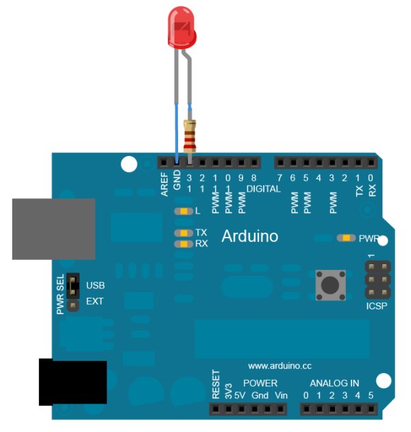
Circuit
To build the circuit, attach a 220-ohm resistor to pin 13. Then attach the long leg of an LED (the positive leg, called the anode) to the resistor. Attach the short leg (the negative leg, called the cathode) to ground. Then plug your Arduino board into your computer, start the Arduino program, and enter the code below.
Most Arduino boards already have an LED attached to pin 13 on the board itself. If you run this example with no hardware attached, you should see that LED blink.
image developed using Fritzing. For more circuit examples, see the Fritzing project page
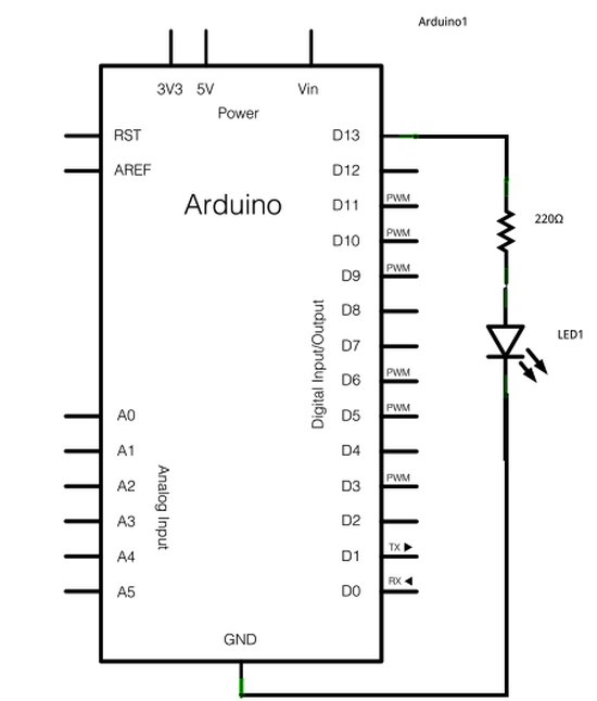
Schematic
Code:
In the program below, the first thing you do is to initialize pin 13 as an output pin with the line
pinMode(13, OUTPUT);
In the main loop, you turn the LED on with the line:
digitalWrite(13, HIGH);
This supplies 5 volts to pin 13. That creates a voltage difference across the pins of the LED, and lights it up. Then you turn it off with the line:
digitalWrite(13, LOW);
That takes pin 13 back to 0 volts, and turns the LED off. In between the on and the off, you want enough time for a person to see the change, so the delay() commands tell the Arduino to do nothing for 1000 milliseconds, or one second. When you use the delay() command, nothing else happens for that amount of time. Once you’ve understood the basic examples, check out the BlinkWithoutDelay example to learn how to create a delay while doing other things.
Hardware Required
- Arduino Board
- LED
For more detail: Blink LED using Arduino
- How do I build the circuit for this project?
Attach a 220-ohm resistor to pin 13, connect the LED anode to the resistor, and the cathode to ground. - Can I run this example without external hardware?
Yes, most Arduino boards have an LED attached to pin 13 that will blink if no other hardware is connected. - What command initializes the pin as an output?
The pinMode function with the arguments 13 and OUTPUT initializes the pin. - How does the code turn the LED on?
It uses digitalWrite with pin 13 set to HIGH, which supplies 5 volts to light the LED. - How does the code turn the LED off?
It uses digitalWrite with pin 13 set to LOW, returning the pin to 0 volts. - Why are delay commands used in the loop?
They pause the program for 1000 milliseconds so a person can see the change in the LED state. - What happens when you use the delay command?
Nothing else happens in the program for the duration of the delay time. - Where can I find examples of creating delays while doing other things?
You should check out the BlinkWithoutDelay example after understanding basic examples.