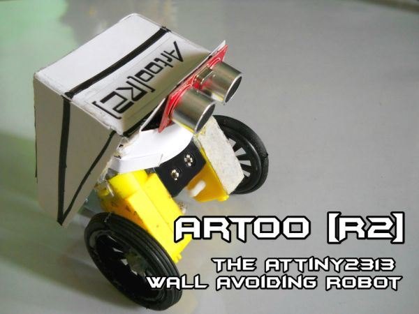
Since I had a lot of ATtiny2313s lying around I wanted to do something cool with them, I thought for a while and then decided to make a simple wall avoiding robot with the ATtiny2313, an ultrasonic sensor and 2 motors.
Its an easy to make and simple robot which runs on a very small amount of code so as to support and work with the ATtiny2313.
For those of you out there who want to make a small robot with the Arduino processing, but you are not able to as the Arduino is too big for a small robot, then this is the perfect robot for you!
Since the ATtiny2313 chip is much smaller compared to the Arduino, it fits in almost anywhere, which allows you to make a small simple robot which evades walls.
Step 1: Materials/Tools Required
Materials Needed;
- ATtiny2313
- Arduino (For programming the ATtiny2313)
- 2 Motors (Gear or normal, both seem to work for me)
- 2 NPN Transistors
- 2 10MicroFarad Capacitors
- 1 5V Voltage Regulator
- 2 9V batteries (Of 250~330mA current capacity each)
- 1 Ultrasonic Range Finder
- A piece of Protoboard
- A few headers (Male)
- 2 Wheels for the motors or some bottle caps might work
- 1 Wheel which is attached to an axis (For attaching it on the back of the robot to give it support)
- A few jumper cables or just some plain wire
- An ATtiny2313 Programming shield (Optional)(http://www.instructables.com/id/Arduino-ATtiny2313-Programming-Shield/)
- 2 9V battery cases or connectors.
- A switch
- Soldering Iron
- Solder
- Soldering Flux
- Glue Gun
- Small cutting knife
- Scissors
Step 2: Adding the Voltage Regulator to the Battery Holder
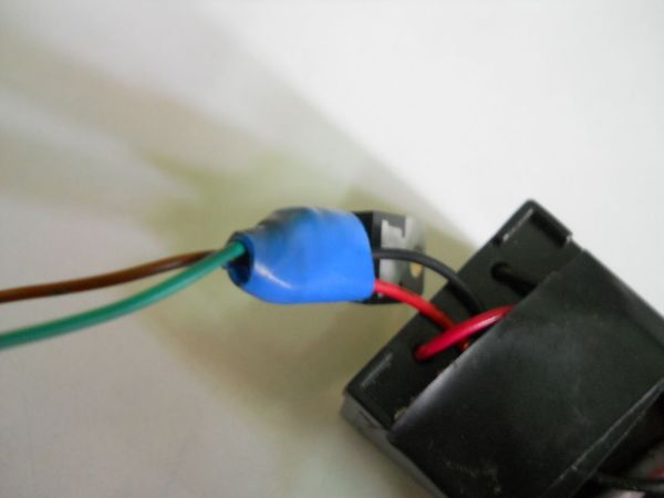
Depending on which 5V voltage regulator you are using, wire it up to the battery case using its 9V and Gnd lines, so that you can take out a 5V and another Gnd line.
These 2 (5V and Gnd) wires will be used to power the ATtiny2313.
Now connect the 5V wire to a switch, so that you can turn on and off the robot as required.
For most 5V voltage regulator, the middle pin is Gnd, the left is Input and right is output, so you can wire it accordingly to get the required Voltage output.
Note: Beware on the voltage regulator you use as a lot of heat is generated by them, and its usually a good idea to add a heat sink to it if you have got one.
(Heat Generated = (Vin-Vout)Iout Joules), Iout is the current output or used by the circuit.
Using the formula, for my circuit I generated about 1kJ so I got away without a heat-sink but if its more than that then you need to be sure to add a heat-sink.
Step 3: Connecting the Ultrasonic Sensor
The Ultrasonic sensor has 5 pins on it whereas the Ping Sensor has only 3 Pins.
In the Ping Sensor, you only have 5V, Gnd and Signal pins where the Signal pin is connected to the arduino to tell us the distance of the object in front of it.
The Ultrasonic Sensor however has 5 pins out of which 4 are used, the 5V and Gnd pins are in common, but instead of the Signal pin you have the Trigger and Echo pins.
Therefore, we have to use these 2 pins in the coding instead of just a Signal pin, so the coding for the Ping Sensor and the Ultrasonic Sensor are different.
In this robot I used an Ultrasonic Sensor as they are usually cheaper than Ping Sensors, I got mine for 9$ at Ebay.
Now, you connect the 5V and Gnd pins of the Ultrasonic Sensor to the 5V and Gnd wires that you got from the battery before using the 5V Voltage Regulator. The Trig pin connects to digital pin 11 of the ATtiny2313 and the Echo pin connects to digital pin 10 of the ATtiny2313.
Step 4: Connecting the Motors and Transistors
The Motors are connected to 1 NPN transistor each so that the ATtiny2313 can control when they turn on and off even when they are based on a 9V circuit and not dependent on the power the ATtiny2313 I/O pins provide. (As the ATtiny2313 pins do not provide enough power to make the motors work)
The Transistors are connected in series with another 9V battery which does not have a 5V Voltage Regulator as the motors I used work off a 9V operating voltage. So I used a 2nd 9V battery to power the motors independent of the rest of the circuit to ensure they get all the power they need to work.
The wiring schematic for this is included in the pictures.
Step 5: Connecting the ATtiny2313 to the rest of the circuit
Pin 10 of the ATtiny2313 is the Ground pin of the board, so it is connected to the Ground that we get from the battery after it has been Voltage Regulated.
Pin 20 of the ATtiny2313 is the Voltage pin where we connect the 5V output from the Voltage regulator.
We also need to connect digital pins 9 and 7 to the center pins of the transistors. (I did not need a resistor as my transistor specifier did not mention any but for majority of transistors we need to add a 1K Ohm resistor to the center pin which then connects to the ATtiny2313)
After doing this you should only have 6 pins on the ATtiny2313 connected and the rest need not be used for this project.
(2 LEDs can be added to 2 pins on the ATtiny2313 if you want to and they can be powered directly by the I/O pins)
Step 6: Assembly of the robot
The 9V battery case will act as the body of the robot.
Attach the 2 motors on either side of the battery case. Attach the Ultrasonic Sensor on top of the battery case and then finally attach the wheel with the axis on the back of the battery case (As shown in the images).
As you can see in the images, I first used small non gear motors but they didn’t work very well and the bot moved quite slowly, so I replaced them with 2 gear motors which run on a very low current (The yellow motors).
The 2nd 9V battery used to power the motors can either be stuck on the front with some hot glue or just left trailing behind.
I decided to leave mine trailing as I attached a small cardboard box around it making it look like a suitcase and the robot has just shifted its home and is searching for a new area to live with its luggage 😀
For more detail: Artoo [R2] (ATtiny2313 Wall Avoiding Robot)