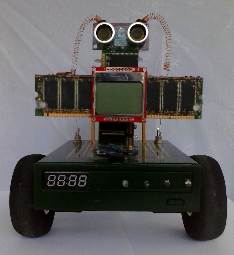
I SHALL CALL HIM ” PEE-WEE ”
Personal Electronics Entertainment With Embedded Education.
Basically a project that is fun and I learn a hole lot of stuff from it.
. This project started out as just a small robot so I could learn more about my Arduino and coding. And at first he was a simple little bot or tot I guess I should say. With a CD player case as a body, a couple of servos and some old laptop speakers with a few LED’s (Gotta have the bells and whistles).
Then one day as I was looking at all the scrap electronics laying around and thinking I will never use most of this crap, What the heck am I keeping it for? Right at that moment the giant ultra bright LED went off in my head!!!
LET’S REALLY BUILD A ROBOT TO HAVE FUN WITH !!!
Step 1: And so it begins.
The following is a how I did it and certainly nothing is written in stone, so be creative. I can’t tell you how many hours I spent looking at some old electronics trying to think of a way for it to serve a purpose in the project, Sometimes it worked out and sometimes it did not(Thank goodness for hot glue). EVERYTHING in this project except the Arduino has been re-purposed from something else, including the wire. Most of it was just plain old junk. I don’t know maybe I’m an electronics hoarder and just don’t know it.The equipment in the pictures is actually in 100% working order. I have both the A and B model scopes and a spare set of tubes for each.
Step 2: Getting the chassis ready
The first thing I did here was to drill out the mounting holes for the stand off insulators that hold the Arduino and Perf board. Also I drilled the hole for a grommet where the drive servos and battery leads go through. Then on the top chassis I drilled the holes for the servo output shaft and the hole for the wire bundle from the head/neck assembly. I then proceeded to drill the holes for the stand offs on the flux capacitor(See step15 for proper spacing) and the hole for that wire bundle in the top chassis.
The next thing that I did was have a few beers and, remove all the labels, then sand, And sand, Have more beer then sand, and sand, Well you get the Idea. The key here is if you want a good finish when your done its PREPARATION PREPARATION PREPARATION !.
The Arduino Uno pictured above was only used for a general idea the actual Arduino
used is a Mega 2560.
Step 3: Painting.
Truly do this how you want and spend the time thinking about it. One tool I used was a simple painting program to draw a box, then I could try a bunch of different schemes with out actually painting.
So I started by Painting the top cover with a couple coats of gold. then masking with 1/8″ pin striping tape after it was COMPLETELY dry. I then lightly sanded the exposed gold. The bottom of the bottom piece was masked off where the servos and battery would go so I would get a good glue joint. Then I painted both top and bottom of bottom a few coats of green and pulled the masking tape off. This first go around did not work due to the fact that I did not use primer. So after sanding it all down AGAIN I primed it first then repeated the previous steps and finally adding three coats of clear coat with a light sanding between each coat.
Step 4: Face plate.
During paint drying times I decided to work on the face plate. I cut the tray front so the four digit display would fit then I hot glued the try front to the face plate. I then sanded and painted the face plate green. After the paint was dry I hot glued the display in place then added the wires for the display.
Step 5: Bottom of the bottom chassis.
First I acquired two Futaba S3004 servos from my R/C junk box and modified them for continuous rotation(Plenty of Instructables on this). The wheels are mounted in the typical way by screwing the servo arms to the wheel hubs. Notice I also mounted the wheels slightly back as apposed to the front. This is to give me better balance and not have to much pressure on the rear wheel or not enough and nose over when stopping.
I then glued a six volt 2000 Mah. battery(Another R/C relic) to the bottom. This battery is used for driving the servo motors.
Next I put the keypad on. It was left over from some lock boxes I made. It has self adhesive backing which makes installation neat and easy.
Most two wheel robots use a caster wheel for the back wheel but I did not have any that I could find although I did all most decommission a piece of luggage for one of the wheels. I did how ever find an R/C tail wheel assembly but could not find a way for it to mount and be sturdy. Then I saw a printer fan and its mounting hole was the exact size of the tail wheel shaft and made a perfect bushing. So although I did not plan on it Pee-Wee now has a cooling fan. The fan is rated at 24 volts but does well enough at 6 volts.
Lastly I hot glued the nine volt battery for the Arduino in place and then routed the wires with dabs of hot glue out and through the grommets.
Step 6: Neck assembly.
So for the neck, as I was looking through a computer junk box I found some old desktop and laptop memory chips. I glued three laptop chips in a triangle length way.
Step 7: Basic head (SCULL).
And for the scull (for lack of a better word) I glued three desktop
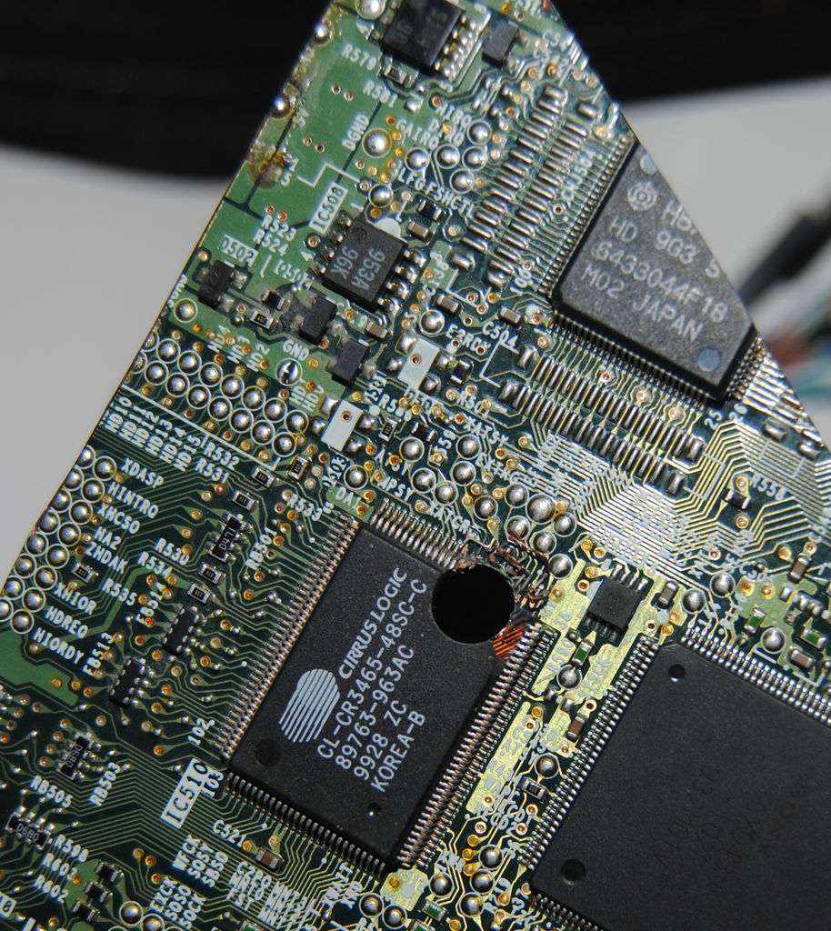
chips end on end in a triangle. For the top of the head I found an old CD ROM circuit board that fit the large triangle and glued it to the triangle first removing any small components to get a good flat bond(This is easily done with a small flat head screwdriver).
Then using a dye grinder I cut the top almost to the edge then
finished with a Dremel and sanding wheel.
Step 8: Mouth and ears.
Now I glued on a Nokia 5110 that was used for another project(To which that project now has a 7″ color touch screen.) to the front of the head. I then added another laptop chip for an upright and glued on an ultrasonic ping sensor.
Step 9: Eyes.
To add some eyes I cut small holes and added RGB LED’s to each side of his head pointing forward.
After calculating the proper resistance using Ohms law for the LED’s I then used my Fluke Lab meter to get the current draw as close to possible to the manufacturers specs. That’s why there are two resistors in series on two of the leads. I could have used the two LED’s in parallel but I wanted to be able to control them separately.
Step 10: Final assembly of head.
Then finally I connected all the wires.
All wires were then run under and into neck.
At the back witch is a corner I cut a slot large enough to let the wires pass freely.
Step 11: Prepairing the head for connection to body.
Now taking a round servo wheel I cut a large hole so that the wire bundle from the head would pass freely. I also made sure the hole was not to big so it could be seen when the neck was in place. I then used a LONG drill bit and drilled a hole in the top of the head. This hole is so I can tighten the screw for the servo arm while attaching the head.
Step 12: Construction of the flux capacitor V-Twin assembly.
This part of the project started from me trying to think of what to do with the hard drive platters I used for the original Pee-Wee.
So again I started rummaging through yet another junk box but this one was all REALLY old electronics. I started with a pair of vacuum tubes that had the same internal structure. I could not go by the numbers because most of them have worn off many moons ago. I then took two red LED’s and hot glued them to the bottom of the tube. I wanted most of the light from the led to go into the tube so I took some black paint and covered all of the hot glue.
For more detail: Arduino V-Twin Flux Capacitor