Story
I have been working out ways to make a minimal Arduino to fit in the smallest space possible, and limit the power consumption of the microcontroller. (You can go through this project for more info about reducing power consumption at: Reducing Arduino Power Consumption). You can assume this one is an extended version of that project.
An Arduino consists of many components like linear regulator, USB to Serial microcontroller, debug LED, power LED, reset button, RX & TX LED, crystal oscillator, etc. But, a minimal circuit can have just the brain of the Arduino UNO that is, an ATmega328p microcontroller.
Making a Minimal Arduino UNO on Breadboard
Most people are successful in making Arduino with minimal circuitry, but use the 16 MHz crystal. We can remove that too, along with 22 pF capacitors. You can configure the ATmega328 to use its internal 8 MHz RC oscillator as a clock source.
Install Support for Hardware Configuration
- Download this hardware configuration archive: breadboard-1-6-x.zip, Breadboard1-5-x.zip or Breadboard1-0-x.zip depending on which IDE you use.
- Create a “hardware” sub-folder in your Arduino sketchbook folder (whose location you can find in the Arduino preferences dialog). If you’ve previously installed support for additional hardware configuration, you may already have a “hardware” folder in your sketchbook.
- Move the breadboard folder from the zip archive to the “hardware” folder of your Arduino sketchbook.
- Restart the Arduino software.
- You should see “ATmega328 on a breadboard (8 MHz internal clock)” in the Tools > Board menu.
Once you’ve done this, you can burn the bootloader and upload programs onto your ATmega328.
Putting Stuff on Breadboard
Get all the stuff listed above in the list. Moreover, get a pin-mapping of the ATmega328P handy while making the circuit.
Using ATmega Without UNO Bootloader
First of all we need to burn the bootloader to the ATmega chip if you bought a blank microcontroller having no bootloader, so that it can be a programmable entity.
- Refer to the schematics and place the ATmega chip in the breadboard.
- Open the ArduinoISP firmware (in Examples) to your Arduino board.
- Select the items in the Tools > Board and Serial Port menus that correspond to the board you are using as the programmer (not the board being programmed).
- Upload the ArduinoISP sketch.
- Select the item in the Tools > Board menu and be sure to select “ATmega328 on a breadboard (8 MHz internal clock)” when burning the bootloader.
- Select the Arduino as ISP in the Tools>Programmer menu.
- Use the Burn Boot-loader command in Tools menu.
Skip step 2 if you have done step 1.
2. Using ATmega with UNO boot-loader
If the ATmega is already boot-loaded, then, just put it in the breadboard and we can proceed for programming the ATmega328p microcontroller.
3. Programming the ATmega chip (using other Arduino)
- Remove the microcontroller of the Arduino you are using as the programmer.
- Refer to the schematics and pin mapping and connect the RX and TX of programmer Arduino to TX and RX of the breadboard Arduino respectively.
- Connect RESET of programmer Arduino to RESET of breadboard Arduino.
- Connect GND and VCC of breadboard Arduino to GND and VCC on programmer Arduino.
- Select the item in the Tools > Board menu and be sure to select “ATmega328 on a breadboard (8 MHz internal clock)”.
- Check the port and click on “upload”.
Plug out the the connections and now you can power it with a battery for months depending on your project kind.
4. Programming the ATmega chip (using FTDI USB to Serial adapter)
Curious what all the pin outs are for the FT232RL breakout board, just simply flip it over! In this situation I’ll be using VCC (to supply 5V from the USB port to your board), GND, TXD, and RXD. [Refer schematics]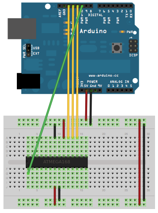
- This board comes without the headers when bought from market. So, solder the male header and plug it in the breadboard.
- Connect RX of ATmega chip to TX of board and TX of ATmega chip to RX of the board.
- Connect VCC and GND to the power rails on the breadboard.
- Plug the USB mini type – B and connect it with your computer and upload the sketch using the Arduino IDE but always remember to select “ATmega328 on a breadboard (8 MHz internal clock)”. It will take power from the USB but after disconnecting the USB, you can plug the battery terminals to the power rails of breadboard.
And the Arduino is ready.
Disclaimer: I would recommend you to make Arduino with internal 8 MHz clock only if your project doesn’t require many command lines to be executed in a very small interval of time. You can use them for projects which are small amount of work after some time repeatedly like water irrigation, solar tracker, etc.
For more detail: Arduino on Internal Oscillator Crystal as Clock Source