Summary of Arduino and 7 Segment Display – Interfacing Tutorial
This tutorial explains interfacing single and 4-digit seven-segment LED displays with an Arduino. It covers the basics of common anode configurations, compares cost-effectiveness against LCDs, and introduces multiplexing for multi-digit setups using shift registers. The guide progresses from a basic 1-digit connection to more complex 4-digit implementations.
Parts used in the Seven Segment Display Interfacing Project:
- Arduino
- Single digit seven segment LED display
- 4 digit seven segment display
- Shift register
In this article, we are publishing a tutorial on how to interface seven segment LED display to Arduino. Seven segment displays are used in many embedded system and industrial applications where the range of outputs to be shown is known beforehand. Basic 1 digit seven segment display can show numbers from 0-9 and a few characters. 7 segment displays are of different types; especially they differ in the number of digits/character it can display. Basically a 7 segment display is a single unit, which can display only 1 digit or 1 character. More digits are displayed by multiplexing single unit 7 segment displays together to form 2 digit display, 3 digit display or 4 digit 7 segment display. Its quiet easy to interface Arduino and 7 Segment display together! Lets begin the tutorial.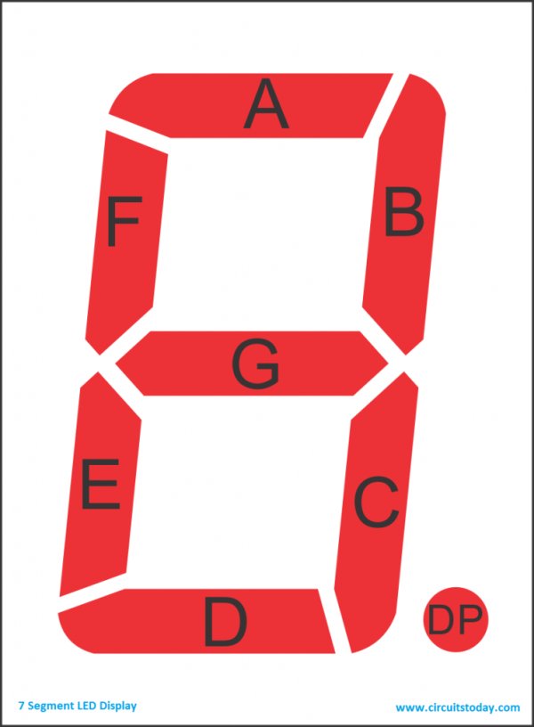
A 7 segment display has many limitations, especially in the range of characters it can display.There are displays in market which are much more advanced than seven segment displays and can display almost every character in the alphabet. For example:- a 16×2 LCD – which can display almost all ASCII characters. You might think why 7 segment display still exist in market. Well, 7 segment displays are the cheapest option when it comes to display devices available in market. A single digit/character 7 segment display unit is available at 1/10th of the cost of a 16×2 LCD module.
We begin this tutorial by interfacing a single digit (1 digit/character) 7 segment LED display to Arduino.Once we learn the single digit 7 segment display interfacing to arduino and its code/program, we move on to interface 4 digit seven segment display with arduino using shift register.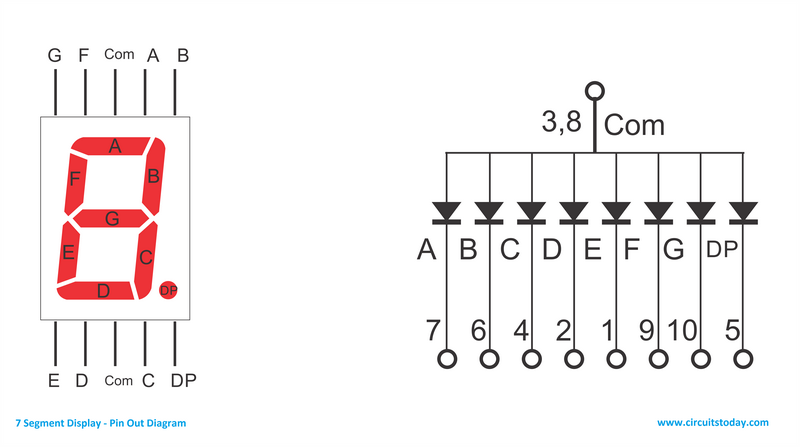 As you can see there are 10 pins in total. You may notice two pins named com, as shown in the circuit diagram all the anodes (+ pins) of the LEDs are connected to these two pins. We call these 2 pins as common anodes and such displays are called Common Anode 7 segment displays.
Read More: Arduino and 7 Segment Display – Interfacing Tutorial
- Why are seven segment displays still used if they have character limitations?
They are the cheapest option available in the market compared to advanced displays like 16×2 LCD modules. - How does the cost of a seven segment display compare to a 16×2 LCD module?
A single digit seven segment display unit is available at one-tenth of the cost of a 16×2 LCD module. - What is the first step in this tutorial regarding the hardware setup?
The tutorial begins by interfacing a single digit seven segment LED display to the Arduino. - How can multiple digits be displayed using these units?
More digits are displayed by multiplexing single unit seven segment displays together to form 2, 3, or 4 digit displays. - What component is used to interface a 4 digit seven segment display with an Arduino?
A shift register is used to interface the 4 digit seven segment display with the Arduino. - How many pins does the described seven segment display have in total?
The display has 10 pins in total. - What are the two pins named com connected to in the circuit diagram?
All the anodes plus pins of the LEDs are connected to these two pins. - What type of seven segment display is created when all anodes are connected to common pins?
This configuration creates a Common Anode 7 segment display.