Summary of Adding CV inputs to the Auduino granular synth
This article details the integration of a Lunetta CMOS noise synth with an Auduino granular synthesizer. The author modifies the Arduino project to accept external control signals via vactrols, enabling voltage control from the 12V Lunetta modules and adding an external gate function. The build involves fabricating a custom panel from PVC fence posts, mounting salvaged potentiometers, and reconfiguring the Auduino code for smooth note mapping to match the chaotic nature of the Lunetta.
Parts used in the Auduino Granular Synth with Lunetta Integration:
- Auduino granular synth unit
- Lunetta CMOS based noise synth
- Vactrols (two units)
- USB cable
- PVC fence posts
- Standard 10k potentiometers
- Bolts, washers, and nuts
- Alligator clip patch cables
- CMS logic chips
- Graph paper
- Sharp awl
- Hand drill
- Colored wires
When I first got into the Arduino I went looking for audio projects. One of the first things I built was TobaTobias’ Auduino granular synth. I was so impressed I built a permanent unit in a heavy duty enclosure and incorporated it into my occasional sets and demos.. This simple project makes really impressive sounds- from clean bass to dirty, brassy highs. Whenever I play out the funky growl of the Auduino granular synth gets people’s attention. With this project I will add inputs so that the Auduino can be controlled by an external sequencer, in this case a Lunetta CMOS based noise synth.
A Lunetta is a DIY sound generator. They are modular, meaning they consist of multiple discrete units. The modules are connected with patch cables- wires with alligator clips that can be rearranged in many ways. Lunettas are built with CMOS logic chips. These chips are the basic building blocks of computers and digital circuits. They are used to create, combine and control binary digital signals- ‘ons’ and ‘offs’. In a typical Lunetta set up the pins of these chips are connected to metal posts. These posts can be connected with the patch wires to create complex circuits that produce tones, rhythmic patterns, melodies and many weird sounds.Here are few tracks made with my Lunetta- Confidence is High and Makeshift Morgue.
For this project I’ll be adding vactrols to allow the 12v from the Lunetta to control the 5v input of the Arduino. I’ll also add another vactrol to act as a gate, turning the output signal on or off with an external signal.
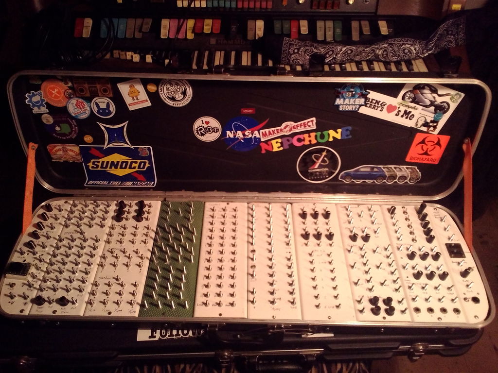
My Lunetta is one of my favorite projects ever! It has over thirty modules- from oscillators and counters to dividers and rate multipliers. It’s built into a gun case that my buddy Gordy rescued from a dumpster. The panels are made from 4″ PVC fence posts cut down to size. I’ve had more use and entertainment out of it than anything else I’ve ever built. I will be building a new one soon and writing an instructable about the process. For now enjoy this introduction.
Step 1: Preparing the Arduino.
I connected my Arduino to the computer with a USB cable and went to the Auduino Instructable and opened the sketch in my editor. I had the choice of how I wanted my granular synth to make notes. It can be set to make a chromatic or pentatonic scale with distinct notes or it can be set to a smooth scale where there are no stepped notes at all. The granular synth I use for performing is set to have stepped pentatonic mapping. This makes it sound very musical. For my Lunetta project I decided to use the smooth note mapping to match the chaotic nature of the instrument. The mapping changes are all explained inside the Auduino code. Be sure to read the Auduino Instructable for a better idea of what we’re doing.
Step 2: Preparing the panel.
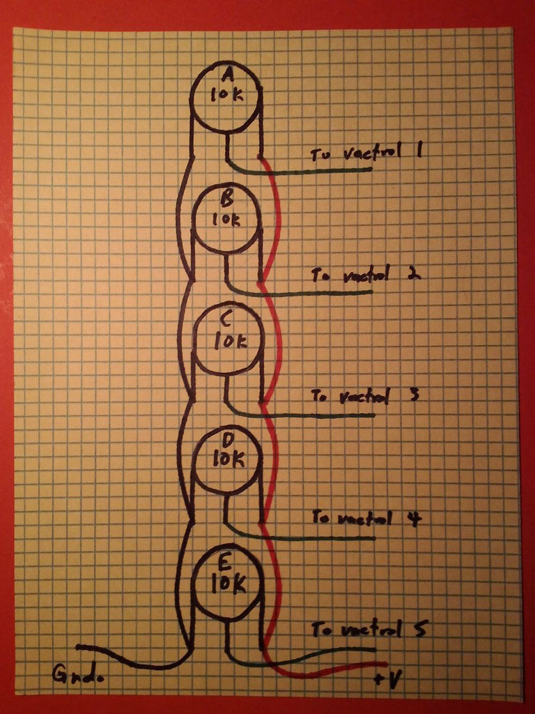
The panels of my Lunetta are made from PVC fence posts. I cut about three inches from the middle of two opposite sides to create two flat panels with right angled short sides for rigidity. This is a really cheap material and it’s very easy to mark and drill. The panel I’m using for the Auduino is at the end of the instrument and is cut to fit the contour of the case. I used graph paper to lay out my posts and pots. The pots are standard 10k pots salvaged from an old mixing board. The posts are made from a bolt, washer and nut. I taped the paper tp the front of the panel and used a sharp awl to mark the center point of each part. I used a hand drill to drill out the holes using appropriately sized bits for the intended part. When everything was drilled I populated the panel to make sure everything would fit. When I was satisfied with the results I removed and wired the pots and reinstalled them with knobs. I wired the common power and ground leads of the individual pots and installed leads to connect to the Arduino’s +5v out and ground. It is important to color code your leads to make it easier to connect everything at the end. By having the same color wire carry the signal from start to finish within the circuit it also makes it much easier to figure out what’s wrong if it doesn’t work right. I started with the top pot and soldered a lead to the center lug- purple, blue, green, yellow and orange respectively. The controls are frequency, pitch A, decay A. pitch B and decay B. I also decided to use white wire for the audio out and gate portion of the circuit. At this point I tested the Auduino by connecting the colored wires to the corresponding analog pins on the Arduino. I connected the common power and ground leads from the pots to the board and connected digital pin 3 to an amp with a ground connection. Everything was A-OK so it was on to the next step.
For more detail: Adding CV inputs to the Auduino granular synth
- What is the purpose of adding vactrols to this project?
Vactrols are added to allow the 12v from the Lunetta to control the 5v input of the Arduino and to act as a gate turning the output signal on or off. - How does the author modify the note mapping for this specific setup?
The author sets the granular synth to use smooth note mapping to match the chaotic nature of the Lunetta instrument. - What material is used to construct the panels for this project?
The panels are made from 4 inch PVC fence posts cut down to size. - Can the Auduino be set to different musical scales?
Yes, the sketch allows the synth to be set to a chromatic scale, a pentatonic scale with distinct notes, or a smooth scale without stepped notes. - Why is it important to color code the leads during wiring?
Color coding makes it easier to connect everything at the end and helps figure out what is wrong if the circuit does not work right. - What type of chips are used to build the Lunetta modules?
The Lunetta modules are built with CMOS logic chips which create, combine, and control binary digital signals. - How are the controls on the panel labeled?
The controls correspond to frequency, pitch A, decay A, pitch B, and decay B. - What tool was used to mark the center points for drilling holes?
A sharp awl was used to mark the center point of each part after taping graph paper to the front of the panel.