Summary of Controlling Hand Drill with Roboduino using Arduino
This article details a DIY project to re-purpose a hand drill into a solder re-spooling machine using a Roboduino, two servos, and a custom optical encoder. The system controls drill speed via servo throttle adjustment and manages solder placement with a guide servo. Key innovations include using flanged bearings for alignment tolerance and a shaft coupling to handle misalignment between different shaft sizes.
Parts used in the Solder Re-Spooling Machine:
- Hand Drill
- Roboduino (Arduino compatible uController)
- Two HS-311 Servos
- (3) Flanged Bearings
- Metal Shafts (1/2" and 1/4")
- Shaft Coupling
- Double Sided Tape
- Laser Printer Encoder Wheel
- Opto Interrupter Sensor
- Masking Tape
- LCD Screen
- Female-Female wires
- Breadboard
- Angle Brackets
- Wood
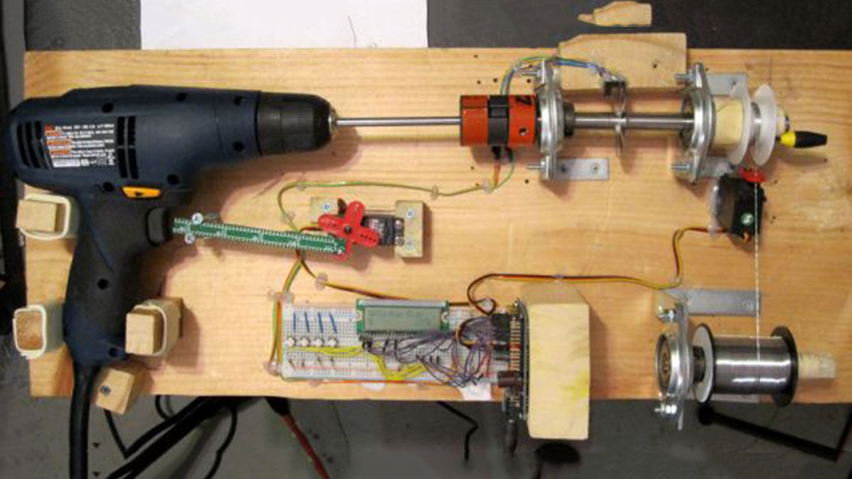
This will explain how we re-purposed a hand drill to re-spool solder using a roboduino (arduino compatible), two servos, and a DIY encoder. While one could use TRIACs to play with the AC power going into the drill, just using a servo to control the throttle is simple and avoids the pesky high voltage.
Hand drills are pretty strong, hopefully this instructable will help others integrate it into other projects,… maybe some guitar pickup winders…
We also talk about using home made optical encoders, which can be used for all sorts of robot applications.
Video:
http://store.curiousinventor.com/blog/controllering_hand_drill_arduino_spool_solder/
Ingredients:
* Hand Drill
* Arduino Code
* uController, arduino / roboduino, something to control servos
* (2) servos, one for throttle, one to guide the solder (we used HS-311s)
* (3) Flanged Bearings These are nice because the bearing can swivel in the flange, eliminating the need for precise alignment
* Various metal shafts–you can get hardened precision shafts from mcmaster, which fit exactly into the bearings. Getting a precisely sized, hardened shaft is more important if there are actual loads in the system (not here!) since the bearings will wear out otherwise. Don’t try to hack saw these babies–you’ll just be grinding down the teeth. Dremel required. A 1/2″ shaft was used for the bearings and a 1/4″ shaft to fit into the drill chuck.
* Shaft Coupling – this is the key to avoiding any hard-to-do precision setup. If you look at the pic, the drill is off angle from the encoder shaft, but the rubber webbing in the shaft coupler makes this a non-issue. It also converts between the different shaft sizes.
* Double Sided Tape – this worked great to hold the drill in place
* Laser Printer to make encoder wheel and an opto interrupter to count the ticks as it turns.
* Masking tape to increase the shaft size to hold the solder spools
* LCD Screen, Female-Female wires, bread board, angle brackets, wood
Tools:
* Hot Glue gun!
* Drill, Saw, Screws (machine and wood), Screw Driver
* Dremel
Step 1: Setting up the home-made encoder
The encoder wheel tells the uController how fast the drill is spinning, which the uController then uses to regulate the speed, deliver the right amount of solder, and control how fast the guide servo sweeps the solder back and forth on the target spool.
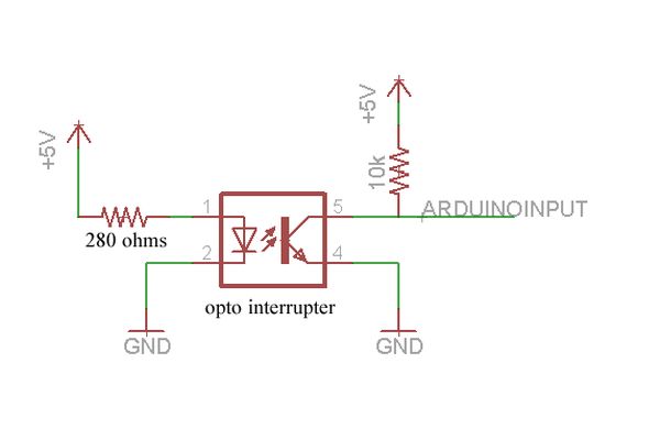
The black U-shaped piece is an opto interrupter, which basically has a beam that gets broken by the encoder wheel. This triggers an interrupt on the roboduino, triggering a function that keeps track of the current speed and number of rotations.
We used this online encoder wheel generator to print out home-made optical encoder wheels on a laser printer. We taped two wheels together with double sided tape to make sure the black parts were opaque enough.
When the sensor sees the light, it turns on and shorts the arduino input to ground. When it’s off, the 10k resistor pulls the line high.
Step 2: Mounting the Drill, Bearings and Shafts
To hold the drill in place, we just traced an outline and screwed in some chunks of wood around the perimeter. Add some double sided tape to get a snug fit.
We use the angle brackets to hold the bearing flange mounts in place. The great thing about these flange mounts is that the bearing can swivel (ball joint style) inside 10-15 degrees before you tighten them down. So we get everything roughly in place, make sure the shafts can spin, and then tighten the flange mounts down.
We use a 1/4″ shaft in the drill chuck and a 1/2″ shaft in the bearings. A 1/4″ shaft was used because the drill chuck only accommodates 3/8″ shafts.
We first tried just wrapping tape around the two shafts to make a couple that matched the ghettoness of the rest of the setup, but that failed horribly after only a few runs. The “spider” coupling from mcmaster provides a backlash free way to connect two different sized shafts that have some angle and axial misalignment. You buy the end pieces and the middle piece separately to fit your shaft sizes… less than $10 overall.
Since there are relatively no loads in this system compared to the 1000 lb capability of these bearings, the solder spool is only supported by a single bearing. One thing we were worried about was the Feeder spool continuing to spin after the Target spool stopped. As it happens, there’s just enough friction in the bearing to stop the Feeder spool, but not so much that the solder wire breaks.
For more detail: Controlling Hand Drill with Roboduino using Arduino
- How is the hand drill's power controlled safely?
The project uses a servo to control the throttle instead of TRIACs, avoiding high voltage AC power. - What component regulates the drill speed?
A home-made optical encoder wheel paired with an opto interrupter tells the uController how fast the drill is spinning. - How are the metal shafts connected to avoid alignment issues?
A shaft coupling with rubber webbing connects the different sized shafts and handles angle and axial misalignment. - Why were flanged bearings chosen for this build?
Flanged bearings allow the bearing to swivel inside the flange, eliminating the need for precise alignment. - What method was used to make the encoder wheels?
The team used an online encoder wheel generator to print wheels on a laser printer and taped two together for opacity. - How does the system prevent the feeder spool from spinning after the target stops?
Friction in the single bearing supporting the spool is sufficient to stop the feeder without breaking the solder wire. - Which specific servo model was used in the project?
The project utilized HS-311 servos, one for the throttle and one to guide the solder. - What tool is required to cut the hardened precision shafts?
A Dremel is required to cut the hardened shafts; hacking saws will just grind down the teeth.