General purpose Arduino shield for self-balancing machines.

Why did I make it?
I previously made an Instructable in 2010 on how to build a self-balancing skateboard.
http://www.instructables.com/id/Easy-build-self-balancing-skateboardrobotsegway-/
There are >500 comments on this and many express confusion setting up the balance sensors, software and electronics. On top of that, the analog output inertial measurement units that were commonly available stopped being made.
Here, I have taken a low price obscure analog IMU that IS currently still made in China, that IS available on ebay, and used an Arduino prototyping “shield” to mount ALL the parts, including a cable to a basic hand-controller (for steering and fine-tuning the balance point) and a cable with just 2 wires that you connect to a 2 x 25Amp “Sabertooth” motor power controller.
I have tried to make it as easy and in particular, non-confusing as possible to build.
NOTE December 2013: Even these are getting rare now but I have just found the “Grove” series of analog sensors from Seedstudio and added contact details to page 6.
In essence a complete re-vamp of the control system, making it simpler to build at the same time.
It works with my self-balancing skateboards but by experimenting with the P, I, and D values listed at the start of the program (Arduino sketch) you should be able to use it to build a SegwayTM clone or similar project.
I have included the basics of how to connect this to the Sabertooth motor power controller, which is an off the shelf commercial robot power controller, how to power the Sabertooth and how to connect the motors to it. For a really detailed explanation of the mechanical side of the build, take a look at my original Instructable of 2010, linked at the top of this introduction page.
One gyro is used for balancing (complementary filter with an accelerometer). Another gyro measures rate of rotation laterally (e.g. when steering).
This provides another useful feature for free; when running in a straight line, if it detects rotation faster than 10 degrees per second laterally, it will change power to the motors to resist this effect. For example the motors often have different friction so when you slow to a stop, one stops before the other and you spin off. This feature stops that happening, and means the wheels can be mounted quite close together.
See this video http://www.youtube.com/watch?v=FEaTxahyQxc and you will see this happening at 0.51 mins, the spare gyro is used to reduce this effect.
Main parts list
www.maplin.com part number GBP US$
N39KR RockerSwitch 2.39 3.62
N39KR RockerSwitch 2.39 3.62
GW72P Microswitch with lever 2.49 3.77
FH04E Sub-Min Toggle switch 2.79 4.23
Project Box 3.79 5.74
XR27E 9 way multicore cable 5.14 7.79
2 core screened cable 0.99 1.50
N30KU Arduino Uno 24.99 37.86
N35KU Arduino protoshield 14.99 22.71
5DOF analog IMU 17.81 26.99
NOTE: List of sellers of this updated August 25th 2013 (See Step 6 for the list)
4 x LED’s 2.56 3.88
_________________________________________________________
80.33 121.71
Step 1: Whole assembly with hand controller
This Instructable assumes you know basics of how to load a program or “sketch” into an Arduino microcontroller and also know how to solder.
Tip:
Even if you think you can see just fine, a pair of magnifying glasses or magnifying visor as sold in many hobby shops makes a huge difference when soldering very small parts and will last you your whole life probably.
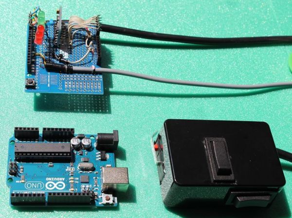
The Shield has long pins that allow you to push it on top of the Arduino when completed. Take care as quite easy to bend some of them as you do it. It has a square grid of solder-holes on which you can mount your own components. I will mount my IMU, my LED indicator lights and the cables to the sabertooth motor controller and the hand controller securely to it also.
The shield is top left in this photograph. Arduino UNO is lower left. Hand controller, which we shall also make is lower right.
Step 2: General build layout of machine
This is just a guide as to how you might lay out the mechanicals of a machine like this using lead-acid sealed batteries and two rear-wheel drive units from a chain driven electric children’s scooter.
See my previous Instructable of 2010 for example of how to arrange the mechanicals.
http://www.instructables.com/id/Easy-build-self-balancing-skateboardrobotsegway-/
Step 3: Main parts laid out
Arduino Uno
Arduino protoshield (or something very similar)
Cable with at least 6 wires inside (mine was 9 core in fact).
Battery holder for 6 x AA 1.5V batteries.
Two rocker switches that return to the middle position on a spring when you let go of them
A microswitch with metal lever that we will use as our deadman switch (when you let go of it all power to motors is cut).
Small on/off switch connecting the battery box to the Arduino.
Connector for the battery box.
Plastic project box which we will make our hand controller from.
Close up of the shield.
The IMU is mounted on it vertically, more on this later (more wires in this early photo than I eventually needed).
We have 4 indicator LED’s.
Multicore cable from hand controller comes in lower left.
2 core cable to Sabertooth motor power controller exits board middle right.
Shield is stacked on top of the Arduino.
Step 5: IMU right angled header pins
In previous photo the IMU was mounted vertically on the Shield. This was because I used right angled header pins to mount it, which conveniently come with the IMU.
Long ends go through edge of board with solder holes along it, short ends go down through holes in the protoshield.
Step 6: How we will wire up the IMU
There are not many analog output IMU’s left out there.
Here is the only one that seems to still be made.
IMU status (Updated 25th August 2013). Constantly changing situation………………….
What you need for this software to work unaltered, is an analog IMU containing an IDG655 gyro and an ADXL335 accelerometer.
This is original one I specified when I wrote the instructable. However now 6 left and price has been quadrupled to $96.99 (thanks guys)
http://www.ebay.com/itm/181004141876?ssPageName=STRK:MEWNX:IT&_trksid=p3984.m1439.l2649
This one looks OK at approx. $17 but note “shipping and handling” is $100 (!) Thanks guys again.
http://www.ebay.com/itm/1PC-5DOF-IDG655-ADXL335-Accelerometer-Dual-axis-Gyro-Instrument-Module/360673380095?rt=nc&_trksid=p2047675.m1851&_trkparms=aid%3D222002%26algo%3DSIC.FIT%26ao%3D1%26asc%3D17214%26meid%3D818663122151966103%26pid%3D100005%26prg%3D8039%26rk%3D3%26rkt%3D5%26sd%3D181004141876%26
This one is OK but listed as sold out
http://www.dhgate.com/product/gy-66-idg655-adxl335-module-5dof-module-twin/156501775.html
Ones that do seem to currently be available at a reasonable price:
GY – 66 5 dof biaxial analog gyroscope sensor IDG655 ADXL335 module
$17.59 Does not ship to UK, does ship elsewhere.
http://www.ebay.com/itm/GY-66-5-dof-biaxial-analog-gyroscope-sensor-IDG655-ADXL335-module-/181115375225
GY-66 IDG655 ADXL335 Module 5DOF Module Twin Screw Analog Quantity Gyroscope Sensor Free Shipping
$14.28
http://www.aliexpress.com/store/product/GY-66-IDG655-ADXL335-Module-5DOF-Module-Twin-Screw-Analog-Quantity-Gyroscope-Sensor-Free-Shipping/406986_729113614.html
This one looks OK. Ships to UK, US etc.
$22.20
http://dx.com/p/gy-66-5dof-idg655-adxl335-double-shaft-analog-quantity-gyroscope-sensor-module-blue-232963
Here it is again at $24.71
http://www.goodluckbuy.com/gy-66-5dof-dual-axis-analog-gyroscope-sensor-module-idg655-adxl335.html
NOTE December 2013: Have just found the “Grove” series of analog sensors from Seedstudio. Details below. The scaling factors in software may need tweaking but at least they are still available to buy:
3 axis analog accelerometer
http://www.seeedstudio.com/wiki/Grove_-_3-Axis_Analog_Accelerometer
Buy here:
http://www.seeedstudio.com/depot/grove-3axis-analog-accelerometer-p-1086.html
and here:
http://www.dawnrobotics.co.uk/grove-3-axis-analog-accelerometer-adxl335/?gclid=CNDQ9fzmqLsCFSoewwod7gYA_w
Also they do an analog 3 axis accelerometer:
Buy here:
http://www.seeedstudio.com/depot/grove-single-axis-analog-gyro-p-1451.html
and here:
http://www.dawnrobotics.co.uk/grove-single-axis-analog-gyro/
Just found these as well (17th Dec 2013)
These also seem to have them in stock:
http://www.dawnrobotics.co.uk/grove-single-axis-analog-gyro/?gclid=COyekqahuLsCFRMRtAodlVMAQA
This one also might work, 10 left on ebay.
http://www.ebay.co.uk/itm/Single-axis-gyroscope-analog-gyro-module-ENC-03MB-module-For-Arduino-MWC-/180956189552?_trksid=p2054897.l4275
You only need one gyro to balance. I use the second one for direction stability but that one is not essential (or buy 2 single axis gyros.
The accelerometer can be bought separately:
Example here:
http://www.ebay.co.uk/itm/ADXL335-3-axis-Analog-Output-Accelerometer-Module-angular-transducer-/281048570799?pt=LH_DefaultDomain_0&hash=item416fccdbaf
Check out how the original one I used was wired up to the Arduino via the protoshield:
Power to the VCC connection is 3.3V from Arduino 3.3V pin, NOT the 5V pin which will blow up the gyros, I know, I have done it before. Take care, these pins and GND are close together on the Arduino and respective protoshield pins, do not let solder bridges form between them! (A good case for the magnifying glasses I mentioned earlier).
GND goes to either GND pin on the protoshield.
Only 3 more connections need to be made:
X4.5 goes to Analog Pin 3 on the Arduino protoshield.
Y4.5 goes to analog pin 2
Z-acc goes to analog pin 1
The rest of the IMU holes you do not have to worry about, not needed………………not too bad was it?
Notes on this IMU:
ACCELEROMETER (ADXL335) notes: 300mV (0.3V) per G i.e. at 90 degree angle
GYRO NOTES on the Chinese IMU we only have available in 2013 which uses the IDG655 gyro module: Gyro outputs x 4.5 on this Chinese IMU: 2.27mV per degree per sec up to 500deg per sec.
Step 7: 3.3V power to the IMU (NOT 5V)
This is how I did it. So long as the wires go to the right pins you can do this any way you like.
I put the long ends of the right angled header pins through the IMU and soldered them all to the respective IMU holes.
From the ends of the long pins (now sticking out horizontally above the Protoshield) I ran small wires carefully to the Analog Pins 1, 2 and 3, you can see this better in the next photograph.
Two longer wires run to the 3.3V power supply pin and also to one of the GND pins.
The holes in the protoshield underneath the IMU are used just to hold the IMU upright and act as a mounting for it. I soldered two of them to hold the IMU rigidly at 90 degrees to the protoshield, i.e. vertically.
The holes on the protoshield just inboard of the black pin sockets are in continuity with them. Therefore you can put header pins in the sockets and solder your wires to them (as seen here with my IMU wires to analog inputs 1,2 and 3) or, you can solder your wires into the holes next to each pin (as seen with the 3.3V wire and GND wire in this photo).
Step 8: Rest of IMU wiring, just 3 wires
As described on previous page, I ran 3 short wires from airborne ends of the IMU long header pins (z-acc, X4.5 and Y4.5) to analog inputs 1, 2 and 3 respectively.
2 more wires go from VCC and GND to 3.3V and GND pins on the protoshield respectively.
For more detail: Self-balancing skateboard/segw*y project Arduino Shield