So my sister managed to break a pan and tilt camera mount and naturally thought daddy can fix this.
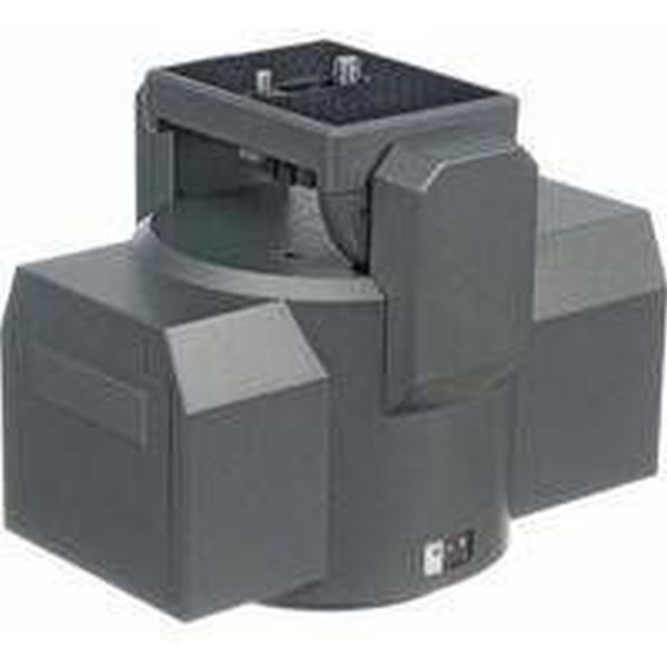
After sitting on my dads workshop bench for a while he had a go at it and couldn’t work out how to fix it so it was passed on to me as broken.
So I decided to hang the current circuit board and lets make this thing arduino compatible and while I am at it lets make it wireless 🙂
In preparation for this I had to work out which wires were for the motors and which were for the internal batteries.
I am working with one of these: http://www.bhphotovideo.com/c/product/64399-REG/Bescor_MP101_MP_101_Motorized_Pan_Head.html
Step 1: Parts required
For this you need some soldering experience and a bit of patience.
Things you’ll need;
Solder
Soldering iron
Two Teensy development boards :- http://pjrc.com/teensy/index.html
An H-Bridge to control the motors :- http://www.ebay.co.uk/itm/SN754410NE-x1-SN754410-754410-Motor-driver-Stepper-Arduino-ATMEGA-PIC-/251042473622?pt=UK_Mobile_Phones_Communication_Radio_Parts_Accessories&hash=item3a734c2696
433 mhz transmitter and receiver :- http://http://www.ebay.co.uk/itm/KDQ6-NEW-1PCS-433MHZ-RF-TRANSMITTER-AND-RECEIVER-LINK-KIT-FOR-ARDUINO-SCA-1710-/360670375378?pt=UK_BOI_Electrical_Components_Supplies_ET&hash=item53f9a12dd2
On Off switch
Step 2: Solder The H-Bridge
When you have the six wires you need from the pan and tilt camera mount you need to attach them to the H-Bridge in the attached format.
You can attach the power directly from the batteries to this allowing for you to power the teensy from the H-Bridge as well as powering the motors.
At this point you can add a switch to turn it on and off when you want.
I assigned the pins as follows
Pin 1, 8, 9, 16 power from the mount.
2,7 pan or tilt pwm respectively
15, 10 pan or tilt pwm respectively
3,6 motor 1
11, 14 motor 2
4, 5, 13, 12 ground
Step 3: Attach the Teensy
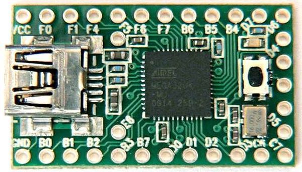
The Teensy will control the whole project.
You need to connect the power from the H-Bridge to the Teensy so it can opperate and you need to connect the PWM wires to four of the data IO’s.
I used pins B5, B6, F7 and F6 as denoted on the board.
From here you can control the pan and tilt by using the teensy’s arduino compatible com port.
To make the mount pan to the right you first need to setup the IO’s. Below is a draft sketch that will make the pan and tilt mount turn constantly to the Right.
int pan[] = {14, 15};
void setup()
{
pinMode(pan[0], OUTPUT);
pinMode(pan[1], OUTPUT);
}
void loop()
{
digitalWrite(pan[0], LOW);//right
digitalWrite(pan[1], HIGH);//right
}
Below is a list of commands that will make the mount pan left, pan right, tilt up, tilt down and stop
int pan[] = {14, 15};
int tilt[] = {16, 17};
digitalWrite(tilt[0], LOW);//up
digitalWrite(tilt[1], HIGH);//up
digitalWrite(tilt[0], HIGH);//down
digitalWrite(tilt[1], LOW);//down
digitalWrite(pan[0], HIGH);//left
digitalWrite(pan[1], LOW);//left
digitalWrite(pan[0], LOW);//right
digitalWrite(pan[1], HIGH);//right
digitalWrite(pan[0], LOW);//stop
digitalWrite(pan[1], LOW);//stop
digitalWrite(tilt[0], LOW);//stop
digitalWrite(tilt[1], LOW);//stop
For more detail: Hacked Pan and Tilt Camera Mount