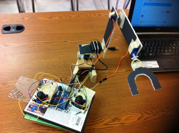
In this instructable I will show you how to make a simple robotic arm controlled by 4 servos , 2 analog joysticks, and an Arduino UNO. It is very similar to my “2 Servos + Thumbstick” instructable. This tutorial is in particular to help out another Arduino user; “RobotZee”.
I will guide you step by step using simple construction parts. Remember this tutorial is to help you out and for you to have an idea on how to make your own robotic arm, using this one as an example. And like my other Arduinos Instructable all the electronic parts were bought @ RADIOSHACK, except for the micro servos. They were bought @ Ebay.
NOTE: The construction of this robotic arm is for examples purposes only. I have use simple and cheap materials for this project.
And this tutorial is to help out other Arduino users on their personal projects. No criticism will be taken personal nor because the construction and materials used for the robotic arm. In other words use this tutorial to built you own and better robotic arm. Thank to all of you…BI()ME(H75
Step 1: Materials & Software
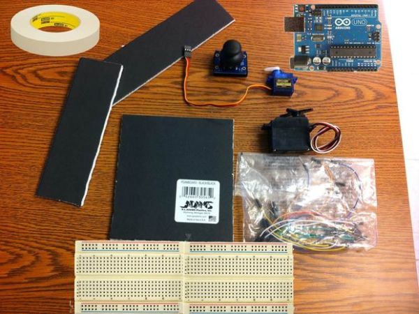
Here is the list in no particular order of the parts, tools and software needed for this project.
Parts:
1. Arduino UNO REV3
2. (2) Bread Boards
3. (2) Parallax servos
4. (2) Ebay micro servos
5. (2) Parallax analog joysticks
6. Breadboard jumper cables
7. Masking Tape
8. Foam board
9. Utility knife, scissors.
10. PATIENCE (a lot)
Software:
Arduino software 0023
NOTE: I rather use this version because the newer one gives me a lot of headaches and issues.
Step 2: Cutting & Assembling Part 1
There is not much to explain in this step. Just cut the foam board any way you want mine is: 6.5 X 1.5 inches and the other one is 4.5 X 1.5 inches. all you have to to is to cut and make holes to fit the servos. Remember the main purpose of this tutorial is to move the servos with the joysticks.
NOTE: Before cutting and putting everything together you need to test the movement of the servos and arrange them in the right place, for the robotic arm and its movements. (after steps 5-8 are complete)
Step 3: Cutting & Assembling Part 2
I have use school tape to hold everything in position. The base is made with recycle pieces of wood that I have found around the garage. Notice how the front servo for the claw rotation it is placed.
Step 4: Cutting & Assembling Part 3
Not much to explain in here, just putting everything together. And I will refer to each connection and servos with a number for your understanding.
EX: Servo 1 base ( body rotation)
Servo 2 arm_1 ( up/down)
Servo 3 arm_2 ( up/down)
Servo 4 claw ( claw rotation)
NOTE: The connections are WAYYY confusing and NOT clear but I will explain them in the next steps.
Step 5: Servos Connections 1 & 2
In here I will show how the connections for the servos 1 and 2.
SERVO 1 is the standard servo for the rotation of the base.
SERVO 2 is another standard servo for the up and down movements of what I refer as ARM_1 .
Servo 1 connections: Red wire: Arduino 5V
Black wire: Arduino GND
Yellow wire: Arduino Digital PWM 10
Servo 2 connections: Red wire: Arduino 5V
Black wire: Arduino GND
Yellow wire: Arduino Digital PWM 11
For more detail: How To Make A Arduino Robotic Arm