Summary of Control a RepStrap with Processing using arduino
This project demonstrates building an open-source CNC system that visually traces the path of a bouncing ball using a RepStrap CNC machine. It integrates hardware like RepStrap McWire Cartesian Bot, Arduino Duemilanove, and stepper drivers with software including Arduino IDE and Processing. The approach involves Arduino firmware and Processing code communicating over serial to control stepper motors driving the X-Y axes. Users can modify the code to alter the bouncing ball's behavior, thus creating different drawings. The project also explores using the Firmata library for alternative motor control methods.
Parts used in the Bouncing Ball CNC Drawing Project:
- RepStrap McWire Cartesian Bot (X-Y Axis CNC Machine)
- Stepper Motor Drivers (RepRap Stepper Motor Driver V1.2 or V2.3)
- PC Power Supply (Desktop Computer PSU)
- Arduino Duemilanove (Atmega 168 chip)
- Arduino Breakout Board v1.4 (or SparkFun Screw Shield)
- USB Cable (Arduino to PC connection)
- Sharpie Marker (as pen tool)
- Wood or Plastic Strip (for pen holder)
- Binder Clips (to secure marker)
- Computer running Arduino IDE and Processing software
This instructable shows how you can use many openly available projects together to build an interesting and complex system. It draws on several community projects including: RepRap, Arduino, Processing, Linux and, of course, Instructables!
More specifically this intructable shows how to draw the path of a bouncing ball with a CNC machine. But this is primarly an example of this open source toolchain.
The first few steps of this intstructable describe the basic setup I am using and includes links to additional information. This is followed by more specific intructions and code to creaste the drawings.
Here is a breif outline of the setup I am using.
Setup:
Hardware:
1 – RepStrap McWire Carestion Bot
2 – Stepper drivers with firmware from RepRap
3 – PC power supply
4 – Arduino Duemilanove
Software:
1 – Arduino IDE on a computer
2 – Processing software on a computer
Here are some good books on Arduino and Processing:
Programming Arduino Getting Started with Sketches
Processing: A Programming Handbook for Visual Designers and Artists
**NOTE** 7/2013 — 3D printing is now pretty popular — there is now an amazon 3D printing store here Amazon 3D printing store
Step 1: The Setup
RepStrap
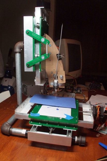
This is “McWire Cartesian Bot v1.2” – It is a version of Tom McGuire’s CNC machine which has been adapted by The RepRap group for 3D printing. For simplicity, this Instructable is only using the X-Y axis. You should be able to use any X-Y stage that is driven with stepper motors.
If you would like to build this exact machine, detailed instructions can be found here (http://reprap.org/bin/view/Main/McWire_Cartesian_Bot_1_2) I believe these were posted by Zach Smith of the RepRap team.
Tom McGurie’s original instructable is here (http://www.instructables.com/id/Easy-to-Build-Desk-Top-3-Axis-CNC-Milling-Machine/)
“Stepper Drivers”
These driver boards are also the work of the RepRap team. They are “Stepper Motor Driver V1.2” Designed by Zach Hoeken. Full instructions can be found at http://reprap.org/bin/view/Main/Stepper_Motor_Driver_1_2. These include ports for optical endstops. This is a very nice feature, but I am not using it here.
They have new version – Stepper Motor Driver v2.3 which is availble here (http://store.makerbot.com/featured-products/stepper-motor-driver-v2-3-kit.html).
SparkFun is stocking a good looking driver as well (http://www.sparkfun.com/commerce/product_info.php?products_id=9402).
“Power”
The power to the drivers is from a desktop computer power supply. RepRap will also tell you how to do this!
http://dev.www.reprap.org/bin/view/Main/PCPowerSupply
“Arduino with breakout”
This setup is using an Arduino Duemilanove with an Atmega 168 chip. Everything should work with other Arduino’s and clones.
This breakout is also from RepRap. It is “Arduino Breakout v1.4” also Designed by Zach Hoeken. And available here. http://store.makerbot.com/electronics/pcbs/arduino-breakout-v1-4-pcb.html
Spark fun is stocking a nice screw sheild as well (http://www.sparkfun.com/commerce/product_info.php?products_id=9282)
“USB cable to PC”
The Arduino is connected to a desktop computer with a USB cable.
“Software on the PC”
I’m running an Ubunto distribution of Linux on my PC, the operating system shouldn’t really matter since this project using Arduino and Processing software which is designed to run on most platforms (Linux, Mac, Windows).
If you don’t already have them, You will need to load the Arduino and Processing software packages.
http://www.arduino.cc/
http://processing.org/
Step 2: Build a pen holder
Ideally you would have a milling tool or plastic extruder mounted on the Z-axis of your desktop CNC machine. Since I have not built those parts for my RepSrap yet, I am using a Sharpie marker clamped to the Z-axis frame.
To build a quick Sharpie holder. Drill a 1/2″ hole in through one end of a strip of wood or plastic (approx 1/4?X1.5″X6″). Wrap a bit of duct tape around the Sharpie for traction. Then stick the sharpie through the hold and clip it inplace with two binder clips, as shown below. This holds reasonalby will and can be quickly adjusted. Once you are ready to start “printint” you just clamp the strip of wood to the fram of the Z-axis, or whatever is handy.
Step 3: Arduino Wiring:
Arduino Wiring:
It is important to have stepper motor drivers wired to the stepper motor correctly. In this case, ‘correclty’ means that the Arduino to Stepper driver connections match the pins called out in the Arduino and Processing Code that follows.
Wire the stepper motor to the Arduino like this:
X – Driver “Arduino” “What it does”
Pin 3 2 Step
Pin 4 3 Direction
Y – Driver “Arduino” “What it does”
Pin 3 10 Step
Pin 4 7 Direction
This is the same setup used by RepRap.org (http://make.rrf.org/electronics-2.0). So if you have a half built RapRap you are all set!
Step 4: Arduino Code
This project requires to peices of code. ‘Firmware’ that is loaded onto the Arduino microcontroller. And ‘Software’ that is run by the Processing program on the PC.
The chain of command goes like this – Processing -> Ardcuino Board -> Steppr drivers -> stepper motors -> X-Y stages.
Here is a little more detail of the communication that will be happening, based on my understanding of the way things work….
The Processing software will send commands to the Arduino board over the USB cable. T The Arduino board will take the command and set the specifed output pins to high or low logic states (5V or 0V). The stepper drivers are wired to the Arduino board outputs. So when the drivers see the high and low signals, they send power to the approriate coils in the stepper motors, making them go.
The code below sets up the Arduino board to listen for the commands sent from Processing and then take actions.
You can cut and paste the code in the Arduino IDE. Then verify the code by clicking the ‘Play” button. If there are no errors you can then upload it to the board by pressing the upload button – which looks like a right arrow.
// Arduino code:
// Read data from the serial and turn ON or OFF a light depending on the value
//and control stepper motor on RepStrap
char val; // Data received from the serial port
int ledPin = 13; // Set the pin to digital I/O 13
#define XstepPin 10
#define XdirPin 7
#define YstepPin 2
#define YdirPin 3
void setup() {
pinMode(ledPin, OUTPUT); // Set pin as OUTPUT
pinMode(XstepPin, OUTPUT);
pinMode(XdirPin, OUTPUT);
pinMode(YstepPin, OUTPUT);
pinMode(YdirPin, OUTPUT);
Serial.begin(9600); // Start serial communication at 9600 bps}
void loop() {
if (Serial.available()) { // If data is available to read,
val = Serial.read(); // read it and store it in val}
if (val == ‘H’) { // If H was received
digitalWrite(ledPin, HIGH); // turn the LED on
digitalWrite(XdirPin,HIGH);
digitalWrite(XstepPin,HIGH);
delayMicroseconds(2);
digitalWrite(XstepPin,LOW);
delayMicroseconds(2);}
if(val == ‘h’) {
digitalWrite(ledPin, HIGH); // turn the LED on
digitalWrite(YdirPin,HIGH);
digitalWrite(YstepPin,HIGH);
delayMicroseconds(2);
digitalWrite(YstepPin,LOW);
delayMicroseconds(2);}
if (val == ‘L’){
digitalWrite(ledPin, LOW); // Otherwise turn it OFF
digitalWrite(XdirPin,LOW);
digitalWrite(XstepPin,HIGH);
delayMicroseconds(2);
digitalWrite(XstepPin,LOW);
delayMicroseconds(2);}
if (val == ‘l’){
digitalWrite(ledPin, LOW); // Otherwise turn it OFF
digitalWrite(YdirPin,LOW);
digitalWrite(YstepPin,HIGH);
delayMicroseconds(2);
digitalWrite(YstepPin,LOW);
delayMicroseconds(2);}
delayMicroseconds(1000); // <<<<<< USE TO CHANGE SPEED <<<<<<<<}
Step 5: Processing Code
Here is the Processing code. Open Processing and cut and paste the code.
This code is built on an example from the Processing text book written by Casey Reas and Ben Fry. (http://www.amazon.com/Processing-Programming-Handbook-Designers-Artists/dp/0262182629)
//This outputs the motion of the bouncing ball to the RepRap X and Y axis
import processing.serial.*;
Serial myPort; // Create object from Serial class
int val; // Data received from the serial port
float x= 50.0;
float y = 50.0;
float speedX = 1.0;
float speedY= .4;
float radius = 15.0;
int timeDelay = 10; //10 ms delay between direction prints gives rocky step
int directionX = 1;
int directionY = 1;
void setup(){
size(100, 100);
smooth();
noStroke();
ellipseMode(RADIUS);
String portName = Serial.list()[0];
myPort = new Serial(this, portName, 9600);}
void draw(){
fill(0,12);
rect(0,0,width, height);
fill(255);
ellipse(x, y, radius, radius);
x += speedX * directionX;
if (directionX == 1){ //if the direction is up, the motor goes one way
myPort.write(‘H’);
print(‘H’);
delay(100);
}
else { // if the direction is down, the motor goes the other way
myPort.write(‘L’); // send an L otherwise
print(‘L’);
delay(100);}
if((x>width-radius) || (x < radius)) {
directionX = -directionX;}
y += speedY * directionY;
if (directionY == 1){ //if the direction is up, the motor goes one way
myPort.write(‘h’);
print(‘h’);
delay(100);}
else { // if the direction is down, the motor goes the other way
myPort.write(‘l’); // send an L otherwise
print(‘l’);
delay(100);}
if((y>height-radius) || (y < radius)) {
directionY = -directionY;}}
Step 6: Run the Processing Code
“Run the Processing Code:”
Confirm that power is OFF to the stepper motors.
Run the Processing code by clicking the ‘Play’ button.
You should see:
1 – A display window on the computer monitor showing the ball slowly bouncing around.
2 – The LEDs on the Arduino and stepper boards blinking.
The H,h,L,l outputs are printed on the bottom of the screen, they are also sent over the USB cable to the Aduino board.
Step 7: Draw!
Draw!
Now that the path of the bouncing ball is being sent to the Arduino Board, it is time to set up the paper and pen.
– Tape a peice of paper to the X-Y platform.
– Clip a pen to the Z-axis frame.
-Check that the ball is still bouning and the lights are still blining.
-Turn on power to the stepper motors!
Step 8: Make changes
Now you can mess around with the code to change the behavior of the ball, which will change the comands to the robot and it will draw somehting different.
Changing the size of the box will make a bigger drawing.
You can also:
Change speed
Change the X or Y bounce
You will probably notice that the steppers are not running very smoothly. I’ll post some new code once this is fixed.
Alternatives and ideas:
-You can do almost this exact instructable using the Arduino “Frimata” library. I don’t know if there is much advantage either way.
-Ultimately would like to print 3D objects that are generated from Processing. I’d like to print 3D fractals, but I am a long way off for now!
Step 9: Making it a little better
As I make improvements I am going to add steps to the end of this instructable.
10-11-09
The previus code tracks the ball pretty well but the steppers are driven in a very rocky way.
In this updated code, the Proccessing sketch only sends a signal to the Arduino when there is a change in direction. So the stepper motors just run in whatever direction they were last set to, until they are told to change. This allows the motors to run alot faster and smoother.
But there is still somthing a bit off. The Arduino seems to miss some of the signals, so the RepStrap ends up with the X-Y stage pushed all the way to one side.
I will try to fix this.
The Arduino and Processing code is below. I have added more comments to help keep things clear.
/////////////////////////////////////////////////
// Arduino code:
// Read data from the serial
//Use data to determine direction of X and Y steppers
#define XstepPin 10
#define XdirPin 7
#define YstepPin 2
#define YdirPin 3
int val; // Data received from the serial port
void setup() {
pinMode(XstepPin, OUTPUT);
pinMode(XdirPin, OUTPUT);
pinMode(YstepPin, OUTPUT);
pinMode(YdirPin, OUTPUT);
Serial.begin(9600); // Start serial communication at 9600 bps
}
void loop() {
int dirX;
int dirY;
if (Serial.available()) { // If data is available to read,
val = Serial.read(); // then read it and store value in val
}
if (val == ‘H’){ //set the direction of X and Y based on data sent from Processing
dirX = HIGH;
}
if (val == ‘L’){
dirX = LOW;
}
if (val == ‘h’){
dirY = HIGH;
}
if (val == ‘l’){
dirY = LOW;
}
digitalWrite(XdirPin,dirX); //set X direction
digitalWrite(YdirPin,dirY); //set Y direction
digitalWrite(XstepPin,HIGH); //take steps
digitalWrite(YstepPin,HIGH);
delayMicroseconds(2);
digitalWrite(XstepPin,LOW);
digitalWrite(YstepPin,LOW);
delayMicroseconds(2);
delayMicroseconds(1000); // <<<<<< USE TO CHANGE SPEED <<<<<<<<}
//Processing Code:
//This outputs the motion of the bouncing ball to the RepRap X and Y axis
import processing.serial.*;
Serial myPort; // Create object from Serial class
int val;
float x= 50.0;
float y = 50.0;
float speedX = 1.0;
float speedY= .4;
float radius = 15.0;
int directionX = 1;
int directionY = 1;
int old_directionX = 1;
int old_directionY = 1;
void setup(){
size(100, 100);
smooth();
noStroke();
ellipseMode(RADIUS);
String portName = Serial.list()[0];
myPort = new Serial(this, portName, 9600);}
void draw(){
fill(0,12);
rect(0,0,width, height);
fill(255);
ellipse(x, y, radius, radius);
x += speedX * directionX;
if((x>width-radius) || (x < radius)) { //change X direction if the ball hits the side of the box
directionX = -directionX;}
y += speedY * directionY;
if((y>height-radius) || (y < radius)) { //change Y direction if the ball hits the side of the box
directionY = -directionY;}
if ((directionX != old_directionX) && (directionX == 1)){ //if X direction changed print H
myPort.write(‘H’);
print(‘H’);
delay(100);}
if ((directionX != old_directionX) && (directionX == -1)){ //if X direction changed print h
myPort.write(‘h’);
print(‘h’);
delay(100);}
if ((directionY != old_directionY) && (directionY == 1)){ //if Y direction changed print L
myPort.write(‘L’);
print(‘L’);
delay(100);}
if ((directionY != old_directionY) && (directionY == -1)){ //if Y direction changed print l
myPort.write(‘l’);
print(‘l’);
delay(100);}
old_directionX = directionX ; //stores the directions we just used, as the old direction
old_directionY= directionY;
delay(100); //uncomment to slow the whole thing down for troubleshooting}
Step 10: Doing it with Firmata
You can learn more about it here:
http://arduino.cc/en/Reference/Firmata
and here:
http://firmata.org/wiki/Main_Page
I don’t understand the details. But, from my experience so far, I do know that is does a good job of handling the communication between the PC and the Arduino. So, I am happy to ignore the details for now.
I have started by modifying an example that is included in theArduinoIDE called “SimpleDigitalFirmata”. Once this code is loaded onto the Arduino, You can communicate with the digital pins on the Arduino board directly from Processing.
In processing I am working from an example that turns on and off an LED on the Arduino board when you move a mouse over a square dawn of the monitor of the PC.
To make Processing control the LED and a Stepper motor, you need to modiify the code for the Arduino and Processing.
On the Arduino side – I’ve defined the stepper pins at the top of the sketch. Then I jammed in code to drive the stepper at the end of the main loop. I put this outside of the code that reads the serial port. So the stepper will just go.
The direction of the stepper is set directly from Processing. The example code turned on and off an LED on pin13. So, I just made the step direction pin do the same thing as the LED.
Here is the code. This only controls the X stepper.
///////////////// ARDUINO //////////////////////
//Supports as many digital inputs and outputs as possible.
//
//This example code is in the public domain.
#include
#define XstepPin 10 //Step pin
#define XdirPin 7 //Direction pin
byte previousPIN[2]; // PIN means PORT for input
byte previousPORT[2];
void outputPort(byte portNumber, byte portValue)
{
// only send the data when it changes, otherwise you get too many messages!
if(previousPIN[portNumber] != portValue) {
Firmata.sendDigitalPort(portNumber, portValue);
previousPIN[portNumber] = portValue;
Firmata.sendDigitalPort(portNumber, portValue);
}
}
void setPinModeCallback(byte pin, int mode) {
if(pin > 1) { // don’t touch RxTx pins (0,1)
pinMode(pin, mode);
}
}
void digitalWriteCallback(byte port, int value)
{
byte i;
byte currentPinValue, previousPinValue;
if(value != previousPORT[port]) {
for(i=0; i<8; i++) {
currentPinValue = (byte) value & (1 << i);
previousPinValue = previousPORT[port] & (1 << i);
if(currentPinValue != previousPinValue) {
digitalWrite(i + (port*8), currentPinValue);
}
}
previousPORT[port] = value;
}
}
void setup()
{
Firmata.setFirmwareVersion(0, 1);
Firmata.attach(DIGITAL_MESSAGE, digitalWriteCallback);
Firmata.attach(SET_PIN_MODE, setPinModeCallback);
Firmata.begin(57600);
}
void loop()
{
outputPort(0, PIND &~ B00000011); // pins 0-7, ignoring Rx/Tx pins (0/1)
outputPort(1, PINB); // pins 8-13
while(Firmata.available()) {
Firmata.processInput();
}
//added stepper sequence to firmata code
digitalWrite(XstepPin,HIGH); //take steps
delayMicroseconds(2);
digitalWrite(XstepPin,LOW);
delayMicroseconds(2);
delayMicroseconds(1000); // <<<<<< USE TO CHANGE STEPPER SPEED <<<<<<<<
}
//////////////////////////////////Processing/////////////////////////////////
/**
* Simple Write. < modified to control stepper direction
*
* Check if the mouse is over a rectangle and writes the status to the serial port.
* This example works with the Wiring / Arduino program that follows below.
*/
import processing.serial.*;
import cc.arduino.*;
Arduino arduino;
//Serial myPort; // Create object from Serial class
// Data received from the serial port
int ledPin = 13; // pin for LED
int XdirPin = 7; // pin for stepper X direction
int XstepPin = 10; //pin for X step
void setup()
{
size(200, 200);
// I know that the first port in the serial list on my mac
// is always my FTDI adaptor, so I open Serial.list()[0].
// On Windows machines, this generally opens COM1.
// Open whatever port is the one you’re using.
// String portName = Serial.list()[0];
//myPort = new Serial(this, portName, 9600);
arduino = new Arduino(this, Arduino.list()[0], 57600); // v1
arduino.pinMode(ledPin, Arduino.OUTPUT);
arduino.pinMode(XdirPin, Arduino.OUTPUT);
}
void draw() {
background(255);
if (mouseOverRect() == true) { // If mouse is over square,
fill(204); // change color and
arduino.digitalWrite(ledPin, Arduino.HIGH); // LED on
arduino.digitalWrite(XdirPin, Arduino.HIGH); // Stepper direction this way
}
else { // If mouse is not over square,
fill(0); // change color and
arduino.digitalWrite(ledPin, Arduino.LOW); // LED off
arduino.digitalWrite(XdirPin, Arduino.LOW); //Stepper direction the other way
}
rect(50, 50, 100, 100); // Draw a square
}
boolean mouseOverRect() { // Test if mouse is over square
return ((mouseX >= 50) && (mouseX <= 150) && (mouseY >= 50) && (mouseY <= 150));}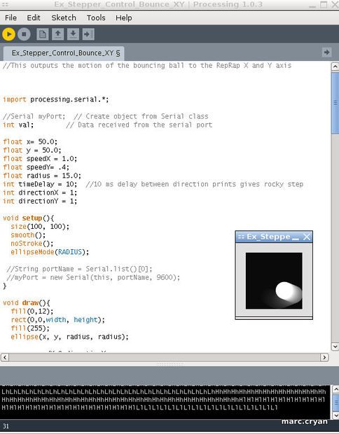
Step 11: Correction to firmata….
The code below works – but doesn’t have as many comments.
//////////////////////////Arduino//////////////////////////
// Wiring/Arduino code:// simmple digital firmata
//Supports as many digital inputs and outputs as possible.
//This example code is in the public domain.
#include <Firmata.h>
#define XstepPin 10
#define XdirPin 7
#define YstepPin 2
#define YdirPin 3
byte previousPIN[2]; // PIN means PORT for input
byte previousPORT[2];
void outputPort(byte portNumber, byte portValue)
{
// only send the data when it changes, otherwise you get too many messages!
if(previousPIN[portNumber] != portValue) {
Firmata.sendDigitalPort(portNumber, portValue);
previousPIN[portNumber] = portValue;
Firmata.sendDigitalPort(portNumber, portValue);
}
}
void setPinModeCallback(byte pin, int mode) {
if(pin > 1) { // don’t touch RxTx pins (0,1)
pinMode(pin, mode);
}
}
void digitalWriteCallback(byte port, int value)
{
byte i;
byte currentPinValue, previousPinValue;
if(value != previousPORT[port]) {
for(i=0; i<8; i++) {
currentPinValue = (byte) value & (1 << i);
previousPinValue = previousPORT[port] & (1 << i);
if(currentPinValue != previousPinValue) {
digitalWrite(i + (port*8), currentPinValue);} }
previousPORT[port] = value;}}
void setup(){
Firmata.setFirmwareVersion(0, 1);
Firmata.attach(DIGITAL_MESSAGE, digitalWriteCallback);
Firmata.attach(SET_PIN_MODE, setPinModeCallback);
Firmata.begin(57600);}
void loop(){outputPort(0, PIND &~ B00000011); // pins 0-7, ignoring Rx/Tx pins (0/1) outputPort(1, PINB); // pins 8-13
while(Firmata.available()) {
Firmata.processInput();
}
//added stepper sequence to firmata code
digitalWrite(XstepPin,HIGH); //take steps
digitalWrite(YstepPin,HIGH);
delayMicroseconds(2);
digitalWrite(XstepPin,LOW);
digitalWrite(YstepPin,LOW);
delayMicroseconds(2);
delayMicroseconds(1000); // <<<<<< USE TO CHANGE STEPPER SPEED???? <<<<<<<<}
/////////////////////////////PROCESSING//////////////////////////////////////
* Simple Write.
*
* Check if the mouse is over a rectangle and writes the status to the serial port.
* This example works with the Wiring / Arduino program that follows below.
*/
import processing.serial.*;
import cc.arduino.*;
Arduino arduino;
//Serial myPort; // Create object from Serial class
// Data received from the serial port
int ledPin = 13;
int XstepPin = 10;
int XdirPin = 7;
void setup()
{
size(200, 200);
// I know that the first port in the serial list on my mac
// is always my FTDI adaptor, so I open Serial.list()[0].
// On Windows machines, this generally opens COM1.
// Open whatever port is the one you’re using.
// String portName = Serial.list()[0];
//myPort = new Serial(this, portName, 9600);
arduino = new Arduino(this, Arduino.list()[0], 57600); // v1
arduino.pinMode(ledPin, Arduino.OUTPUT);
arduino.pinMode(XstepPin, Arduino.OUTPUT);
arduino.pinMode(XdirPin, Arduino.OUTPUT);
}
void draw() {
background(255);
if (mouseOverRect() == true) { // If mouse is over square,
fill(204); // change color and
arduino.digitalWrite(ledPin, Arduino.HIGH); // send an H to indicate mouse is over square
arduino.digitalWrite(XdirPin, Arduino.HIGH);
//arduino.digitalWrite(XstepPin, Arduino.HIGH);
//delay(1);
//arduino.digitalWrite(XstepPin, Arduino.LOW);
//delay(1);
}
else { // If mouse is not over square,
fill(0); // change color and
arduino.digitalWrite(ledPin, Arduino.LOW); // send an L otherwise
arduino.digitalWrite(XdirPin, Arduino.LOW);
//arduino.digitalWrite(XstepPin, Arduino.HIGH);
//delay(1);
//arduino.digitalWrite(XstepPin,Arduino.LOW);
//delay(1);
}
rect(50, 50, 100, 100); // Draw a square
}
boolean mouseOverRect() { // Test if mouse is over square
return ((mouseX >= 50) && (mouseX <= 150) && (mouseY >= 50) && (mouseY <= 150));}
Step 12: Corrected and commented
Here is a third pass at the Firmata code.
This should work and includes comments.
///////////////// ARDUINO //////////////////////
/* Supports as many digital inputs and outputs as possible.
*<modified to drive a stepper motor
* This example code is in the public domain.
*/
#include <Firmata.h>
#define XstepPin 10 //Step pin
#define XdirPin 7 //Direction pin
byte previousPIN[2]; // PIN means PORT for input
byte previousPORT[2];
void outputPort(byte portNumber, byte portValue)
{
// only send the data when it changes, otherwise you get too many messages!
if(previousPIN[portNumber] != portValue) {
Firmata.sendDigitalPort(portNumber, portValue);
previousPIN[portNumber] = portValue;
Firmata.sendDigitalPort(portNumber, portValue);
}
}
void setPinModeCallback(byte pin, int mode) {
if(pin > 1) { // don’t touch RxTx pins (0,1)
pinMode(pin, mode);
}
}
void digitalWriteCallback(byte port, int value)
{
byte i;
byte currentPinValue, previousPinValue;
if(value != previousPORT[port]) {
for(i=0; i<8; i++) {
currentPinValue = (byte) value & (1 << i);
previousPinValue = previousPORT[port] & (1 << i);
if(currentPinValue != previousPinValue) {
digitalWrite(i + (port*8), currentPinValue);
}
}
previousPORT[port] = value;
}
}
void setup()
{
Firmata.setFirmwareVersion(0, 1);
Firmata.attach(DIGITAL_MESSAGE, digitalWriteCallback);
Firmata.attach(SET_PIN_MODE, setPinModeCallback);
Firmata.begin(57600);
}
void loop()
{
outputPort(0, PIND &~ B00000011); // pins 0-7, ignoring Rx/Tx pins (0/1)
outputPort(1, PINB); // pins 8-13
while(Firmata.available()) {
Firmata.processInput()}
//added stepper sequence to firmata code
//digitalWrite(XdirPin,HIGH);
digitalWrite(XstepPin,HIGH); //take steps
delayMicroseconds(2);
digitalWrite(XstepPin,LOW);
delayMicroseconds(2);
delayMicroseconds(1000); // <<<<<< USE TO CHANGE STEPPER SPEED <<<<<<<<
For more detail: Control a RepStrap with Processing